Otto Cycle – Definition, PV Diagram and TS Diagram:
It is an idealized cycle for the spark ignition internal combustion engines. It is the thermodynamic cycle most commonly found in automobile engine. Otto Cycle was conceived by Nikolaws Otto. It is the standard of comparison for internal combustion engine and a description of what happens to a mass of gas when it is subjected to changes like pressure, temperature, volume, addition of heat, removal of heat.
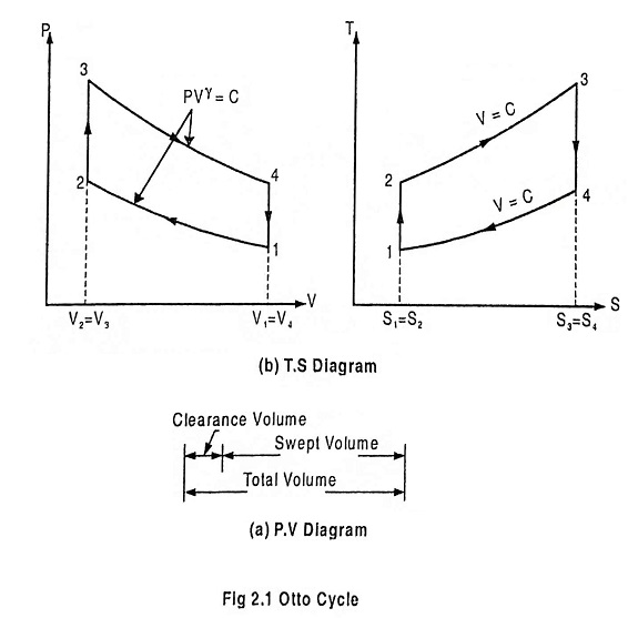
Fig. 2.1 shows the theoretical P-V diagram and T- s diagrams of this cycle.
The otto cycle consists of four processes 1 – 2 – 3 – 4
Refer the P-V diagram and T- s diagram.
Process 1-2: Reversible adiabatic compression of air:
In this process, the piston moves from BDC to TDC position. Air undergoes reversible adiabatic compression. Hence the volume of the air decreases from V1 to V2 and the pressure increases from P1 to P2. Temperature increases from T1 to T2 as it is an isentropic process and the entropy remains constant S1 = S2.
Process 2-3: Heat addition at constant volume:
It is a isochoric (constant volume) heat addition process. Here the piston remains at TDC for a moment. Heat is added at constant volume V2 = V3 from an external heat source. Temperature increases from T2 to T3, pressure increases from P2 to P3 and entropy increases from S2 to S3.
In this process
![]()
Where
- m = mass
- Cv = Specific heat at constant volume
Process 3-4: Reversible adiabatic expansion of air:
In this process, air undergoes isentropic (reversible adiabatic) expansion of air. The piston is pushed from TDC to BDC position. The pressure decreases from P3 to P4, volume rises from V3 to V4, temperature decreases from T3 to T4 and the entropy remains constant (S3 = S4).
Process 4-1: Heat rejection at constant volume:
In this process, the piston remains at BDC for a moment and heat is rejected at constant volume (V4 = V1). The pressure falls from P4 to P1. The temperature decreases from T4 to T1 and entropy falls from S4 to S1.
In this process
![]()

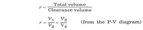
The compression ratio (r) in the ratio of total volume to the clearance volume.
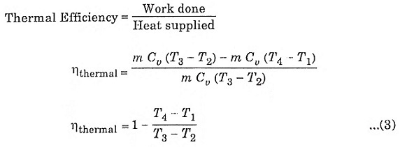
Expression for air-standard efficiency of otto cycle.
To derive ηotto, we must first derive T2 and T3 from the process 1-2 and process 3-4 respectively.
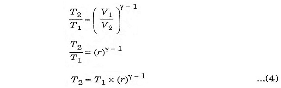
Process 1-2:
It is an isentropic process, therefore the relation between T and V is as follows.
Process 3-4:
It is also an isentropic process, therefore the relation between T and V is similar to process 1-2.
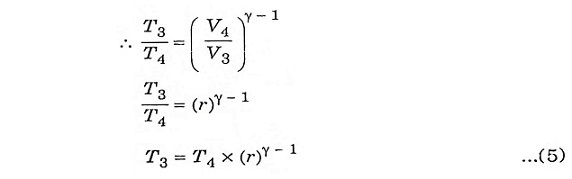
Substituting the values of equation 4 and 5 in equation 3.
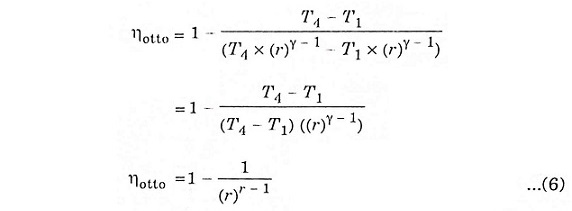
The above expression shows that efficiency increases with the increase of compression ratio.