Diesel Cycle – Definition, Process, PV Diagram and TS Diagram:
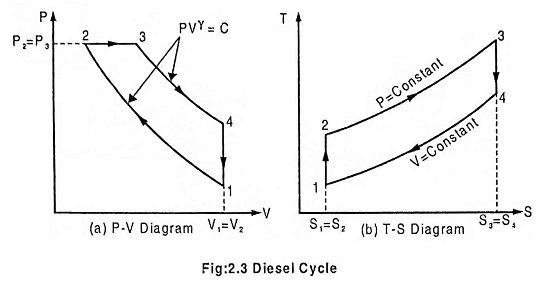
Diesel Cycle was introduced by Rudolph Diesel in 1897. It is the cycle used in the Diesel (compression-ignition) engine. The heat is transferred to the working fluid at constant pressure. The Fig. 2.3 below shows the PV and T-s diagram of a Diesel cycle.
The Diesel cycle comprises of the following operations
Process 1-2: Adiabatic compression:
In this process, the piston moves from BDC to TDC position. The air is compressed adiabatically with a compression ratio typically between 15 and 20. The compression rises the temperature of the air and leads to ignition temperature of the fuel mixture formed by injecting fuel. The pressure rises from P1 to P2, the volume decreases from V1 to V2, the temperature increases from T1 to T2 and the entropy remains constant (S1 = S2).
Process 2-3: Addition of heat at constant pressure:
In this process, the piston remains at TDC position for a moment. Heat is added at constant pressure (P2 = P3) by injection of fuel and combustion. The volume of the mixture increases from V2 to V3, the temperature increases from T2 to T3 and entropy increases from S2 to S3.
Process 3-4: Adiabatic expansion:
In this process, the piston moves from TDC to BDC position. It is the power stroke of the cycle. The air expands adiabatically thus the volume increases from V3 to V4, the temperature decreases from T3 to T4, pressure decreases from P3 to P4 and the entropy remains constant (S3 = S4).
Process 4-1: Heat rejection at constant volume:
In this process, the piston remains at the BDC position for a moment. Heat is rejected at constant volume (V1 = V4). The pressure decreases from P4 to P1, the temperature decreases from T4 to T1 and the entropy decreases from S4 to S1.
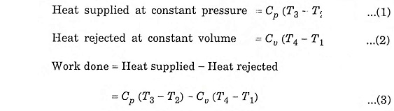
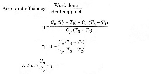
In the cycle consider for unit mass

Let compression ratio

and cut off ratio

To derive η, we must derive T2, T3 and T4 from the process 1 – 2, process 2 – 3 and process 3 – 4 respectively.
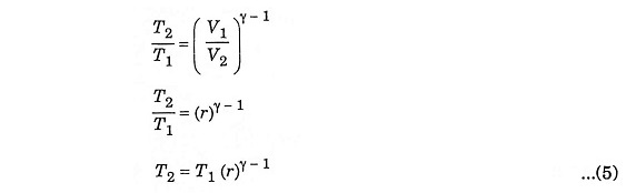
During adiabatic compression 1 – 2
During constant pressure 2 – 3

Substituting the value of T2 from equation (5)
![]()
During adiabatic expansion 3 – 4
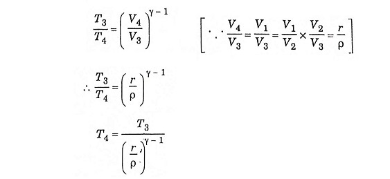
Substituting the value of T3 from equation (6)

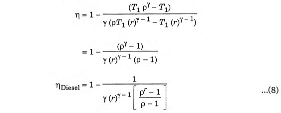
Inserting equation (5), (6) and (7) in equation (4), we get