Diesel Electric Traction System:
Because of high initial cost, electric traction is justified only where there is sufficient volume of traffic. Diesel Electric Traction System is preferable where the traffic is limited. Boundary between these two alternatives depends on several factors such as initial cost, running cost, amount of traffic, maintenance etc. Diesel Electric Traction System is employed both for locomotives and motor coaches. As in electric traction, the locomotives are used in main line traction. Motor coaches are employed in branch lines with low traffic densities and are not used in suburban trains. Diesel electric locomotives are also used for transporting material in steel plants.
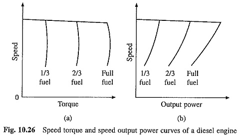
A diesel engine cannot function at low speeds and hence cannot be directly coupled to the driving wheels. It is employed at about its most favourable value of constant speed and power is transmitted to the driving wheels using either electric or hydraulic transmission. Both transmissions function like a gear system whose tooth ratio can be changed steplessly over a large range. The speed-torque and speed-power characteristics of a diesel engine for different levels of fuel injection are somewhat as shown in Fig. 10.26. These characteristic may vary with the type of engine, method of fuel injection, speed of working and degree of supercharging; but the nature remains as shown in Fig. 10.26. The torque is roughly independent of speed over an appreciable range, but tends to decrease somewhat at higher speeds. The value of speed corresponding to maximum power is fairly critical. Engine is, therefore, driven at the optimum speed and electric transmission (or torque converter) is used to transmit power to the driving wheels in a manner most suited to the traction load.
Several electric transmissions have been used, the most common ones are:
- Diesel engine driven de generator feeding dc series motor.
- Diesel engine driven three phase alternator supplying dc series traction motors through semiconductor diode rectifier.
- Diesel engine driven alternator feeding squirrel-cage motors through diode rectifier followed by 3-phase voltage source inverter.
Diesel Engine Driven dc Generator Feeding dc Series Motors:
Block diagram of the scheme is shown in Fig. 10.27.
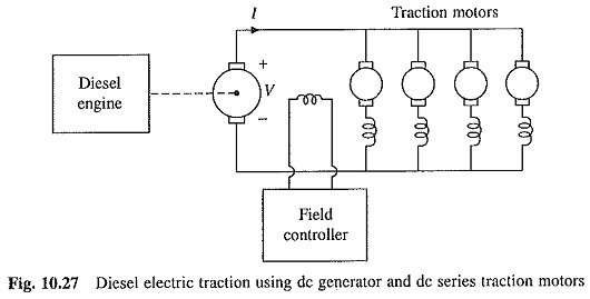
Diesel engine has a very small overloading capacity. Even a 10% overload results in stalling the engine. It becomes necessary to modify the generator characteristics so that overloading of the diesel engine can be avoided. Desired V-I characteristic of the generator are shown in Fig. 10.28.
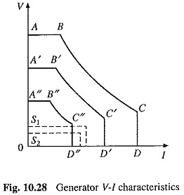
The ideal system of electric transmission for Diesel Electric Traction System locomotive is one in which full horse power of the engine can be utilised by conversion into tractive effort over the wide range of locomotive speeds, i.e. for a given fuel injection the generator output power must be held constant regardless of speed of the traction motors. When operating at full fuel injection, part BC of the characteristic ABCD ensures operation of the generator at constant power (V x I = constant). Part CD is obtained by imposing a limit on generator current for: (i) protecting the generator and motor and (ii) to limit the traction motor torque. Too high traction motor torque can produce two undesirable results: (1) with high adhesion between locomotive’s driving wheels and rails, draw bar fracture might result, and (2) with low adhesion, slipping of driving wheels might result. Part AB is realised by imposing generator voltage limit so that: (a) generator and motor voltages do not exceed the rated value, and (b) motor speed will remain within a safe limit.
For lower diesel engine fuel injections, generator has the characteristics A’B’C’D’ and A”B”C”D” etc. Parts B’C’ and B”C”of these characteristics represent operation at a constant power. Current limits C’D’ and C”D” and voltage limits A’B’ and A”B”are incorporated for smooth acceleration and to deal with varying conditions of track related to slope, and condition and strength of rails.
The characteristics S1 and S2 are provided for shunting.
Diesel engine does not have Starting Torque. It is started by making generator to work as a motor. For this the generator may be fed from a battery.
Diesel Engine Driven Three Phase Alternator Supplying dc Motors:
Figure 10.29 shows the circuit diagram of a Diesel Electric Traction System locomotive using a brushless alternator. The dc series traction motors are supplied through two diode bridges. Excitation of an alternator is usually obtained by feeding dc into the rotor by means of slip-rings and brushes which require frequent maintenance.
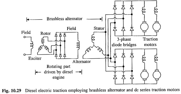
In the present scheme brushes and slip-rings are eliminated by the use of brushless excitation system. It employs an exciter which is an alternator with inverted rotor and stator functions, i.e. field is on the stator and three phase ac winding on the rotor. Exciter is mounted on the shaft of alternator. Three phase voltages induced in the rotor of exciter are rectified by a diode bridge which is mounted on the rotor shaft, and therefore, revolves with it. The rectified voltage is fed to the field of the alternator. Alternator field adjustment is done by the control of exciter field current.
This scheme has following advantages compared to dc generator scheme of Fig. 10.27:
- Because of low maximum speed, the maximum power rating of a dc generator is low. By the use of an alternator, maximum power rating of a Diesel Electric Traction System locomotive can be increased.
- Reduction in the weight of generating unit by around 50%. It also brings down the volume and cost of generating unit.
- Use of brushless alternator results in reduced maintenance.
- Efficiency of transmission is improved by 2-4%.
- With the cost of alternator-rectifier being less and with lower maintenance the scheme is more economical.
- Advantage of good adhesion is retained due to parallel connection of all motors.
The only disadvantage of alternator-rectifier scheme is that the engine cannot be started by this arrangement. A separate starting motor is provided for this purpose.
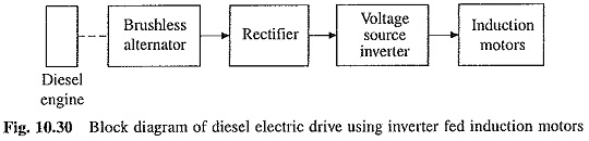
Diesel Engine Driven Alternator Feeding Squirrel-Cage Induction Motors Through Diode-Bridge and Inverter.
Figure 10.30 shows the block diagram of this scheme. Both six-step and PWM inverter can be used. When six-step inverter is used voltage control is provided by adjustment of alternator field current. When PWM inverter is used, voltage control is provided by the inverter itself and the rectifier output voltage can be maintained constant at the rated value. This allows reduction in the current rating of alternator and diode rectifier; further reducing the cost, weight and size of the generating unit. A cycloconverter can also be used instead of diode rectifier and inverter. But then the alternator must be driven at a higher speed.
Because of the use of squirrel-cage motors, alternator and inverter, this scheme has following advantages:
- High ratio of power output, to locomotive weight. The locomotive can therefore pull heavier trains on faster schedules.
- power rating.
- Reduced maintenance and overtime.
- High efficiency due to low power losses.
- All motors can be connected in parallel providing best condition from the point of view of adhesion.