Contactor Type Controller in Electric Traction:
Contactor Type Controller – Schematic power diagram of a 1,500 V dc train equipment consisting of 4 dc series motors wired for series-parallel operation during starting, in its simplified form is shown in Fig. 13.12.
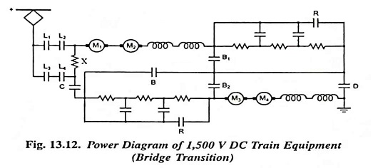
Motors M1 and M2 are connected in series and have three breaks L1 and L2 and D. Motors M3 and M4 are also connected in series and have three breaks L3, L4 and C.
Bridging contactors B1 and B2 have full line voltage of 1,500 V across them when the motors are in parallel and for this reason there are two breaks. Resistance X is inserted in the circuit to protect the system at switch on in case of fault in any motor.
In the starting position line switches L3, L4 and bridging contractor B close and then line switches L1 and L2. Now motors M1, M2, M3 and M4 are in series with full starting resistance in the circuit. Then contactors R operate on the following notches and takes the starting resistances out of circuit in steps, the motors are running in series on the full line voltage.
Then bridging contactors B1 and B2 close and B opens, the motors still operate in series but with no external resistance in the circuit. The contactors R then open, B1 and B2 open, C and D close, placing the motors in parallel with full starting resistance in the circuit. The contactor type controller R then take the starting resistances out of circuit in steps and finally the required arrangement is obtained.