Drum Controller for DC Series Motor:
DC series motors are often employed on cranes, elevators, tramcars and other applications, where the motor is under the direct control of an operator. In these applications, frequent starting, variations of speed, stopping and reversing may be necessary. A manually operated controller, more rugged than a starting rheostat, called a drum controller, is employed.
The Drum controller is in the form of rotating drum having segments which makes contact with the fixed points. Speed controller of this type is shown in Fig. 1.62 in which K is an arc braking coil: EM is a braking electromagnet; FLS is a switch for rotation in one direction and RLS is a switch for rotation in reverse direction. The drum controller has six positions for forward and six positions for reverse rotation of the motor. The working positions of the controller are shown by vertical dotted lines. The electromagnet EM, is connected in parallel with the motor and releases the motor at starting. When the motor is disconnected it is braked mechanically.
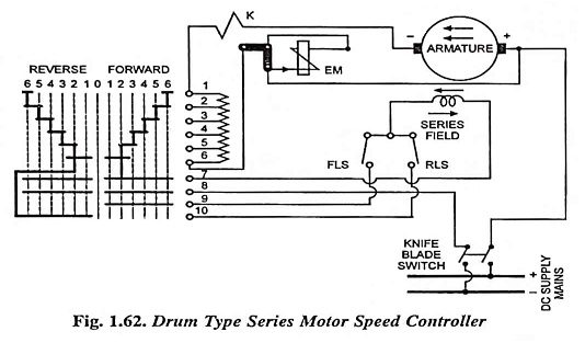
Now when the knife blade switch is closed and the controller is set in forward position 1, the connections are along vertical line one. In this position segments make contacts with fixed points 6 and 7, 8 and 9. In this position current flows from +ve bus-bar through armature winding of the motor, arc braking coil K, all the starting resistances 1-6, fixed points 6 and 7 through controller segments, series field winding, the forward limit switch FLS, fixed points 9 and 8 through controller segments and returns back to the negative bus-bar.
In the second forward position, the segments of the drum controller come in contact with fixed points 5 and 6 thereby bringing some of the starting resistance out of circuit, so speed of the series motor increases. In the subsequent forwarding positions 3rd, 4th and 5th, additional steps of the starting resistances are brought out of the circuit and finally in 6th position all the starting resistances are short circuited and motor attains maximum speed.
In all the six forward positions the direction of current in armature as well as in series field winding is same (from right to left), as shown in Fig. 1.62.
But in first reverse position the current flows from + ve bus-bar through armature winding, arc braking coil K, all the starting resistances 1-6, fixed points 6 and 10 through controller segments, the reverse limit switch RLS, the series field winding, fixed points 7 and 8 through controller segments and returns back to the – ve bus-bar. Hence it is obvious that in reversing positions direction of flow of current in armature winding remains unchanged, while reverses through the series field winding, thereby reversing the direction of rotation of motor.