8257 DMA Controller:
In microprocessor based systems data transfer can be controlled by either software or hardware. Upto this point we have used program instructions to transfer data from I/O device to memory or from memory to I/O device. To transfer data by 8257 DMA Controller method microprocessor has to do following tasks :
-
To fetch the instruction
-
To decode the instruction and
-
To execute the instruction.
To carryout these tasks microprocessor requires considerable time, so this method of data transfer is not suitable for large data transfers such as data transfer from magnetic disk or optical disk to memory. In such situations hardware controlled data transfer technique is used.
Software Controlled Data Transfer:
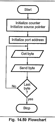
In this method programmer executes a series of instructions to carry out data transfer. The sample flow chart and program required to transfer data from memory to I/O device is shown in Fig. 14.59.
Hardware Controlled Data Transfer:
In this technique external device is used to control data transfer. External device generates address and control signals required to control data transfer and allows peripheral device to directly access the memory. Hence this technique is referred to as Direct Memory Access (DMA) and external device which controls the data transfer is referred to as DMA controller. Fig. 14.60 shows that how DMA controller operates in a microprocessor system.
DMA Idle Cycle:
When the system is turned on, the switches are in the A position, so the buses are connected from the microprocessor to the system memory and peripherals. Microprocessor then executes the program until it needs to read a block of data from the disk. To read a block of data from the disk microprocessor sends a series of commands to the disk controller device telling it to search and read the desired block of data from the disk. When disk controller is ready to transfer first byte of data from disk, it sends DMA request DRQ signal to the DMA controller. Then DMA controller sends a hold request HRQ signal to the microprocessor HOLD input.
The microprocessor responds this HOLD signal by floating its buses and sending out a hold acknowledge signal HLDA, to the DMA controller: When the DMA controller receives the HLDA signal, it sends a control signal to change switch position from A to B. This disconnects the microprocessor from the buses and connects 8257 DMA Controller controller to the buses.
DMA Active Cycle:
When DMA controller gets control of the buses, it sends the memory address where the first byte of data from the disk is to be written. It also sends a DMA acknowledge, DACK signal to the disk controller device telling it to get ready for data transfer. Finally (in case of DMA write operation), it asserts both the IOR and MEMW signals on the control bus. Asserting the IOR signal enables the disk controller to output the byte of data from the disk on the data bus and asserting the MEMW signal enables the addressed memory to accept data from the data bus. In this technique data is transferred directly from the disk controller to the memory location without passing through the CPU or the DMA controller.
When the data transfer is complete, the 8257 DMA Controller unasserts the HOLD request signal to the microprocessor and releases the bus by changing switch position from B to A. After getting the control of all buses the microprocessor executes the remaining program.
