8259A Programmable Interrupt Controller:
8259A Programmable Interrupt Controller – Microprocessor-based system design requires many I/O devices such as keyboards, displays, sensors and other components. These devices should receive servicing in an efficient manner from the CPU. The most common method of servicing such devices is known as the polled approach. In this approach, the processor must test each device in sequence and find the device that requires servicing. For this, a large portion of the main program is looped through this continuous polling cycle. Such a method would have a serious detrimental effect on system throughput, thus limiting the tasks that could be assumed by the microprocessor and reducing the cost effectiveness of using such devices. The other most desirable method is that the microprocessor can execute its main program and only stop to service peripheral devices when CPU receives a signal from the device itself.
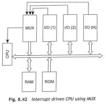
Then the processor should complete whatever instruction is currently being executed and fetch a new routine that will service the requesting device. However, after completion of service, the processor would resume exactly where it left off. This method is known as interrupt. Interrupts are used in a microcomputer system for different applications. When the number of I/O devices are less, the already available interrupts of microprocessors are sufficient and there is no requirement of programmable interrupt controller as shown in Fig. 8.42.
The CPU can access many devices using interrupt signals. In multiple interrupt systems, the CPU must take care of the priorities for the interrupts and simultaneously occurred interrupts.
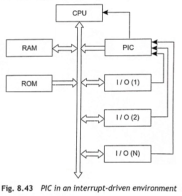
To overcome all difficulties, a Programmable Interrupt Controller (PIC) has been designed and can be used to handle many interrupts at a time. This controller handles all simultaneous interrupt requests along with their priorities and the microprocessor will be relieved from this task. The Programmable Interrupt Controller (PIC) functions as an overall manager in an interrupt-driven system environment as depicted in Fig. 8.43. It accepts requests from the peripheral equipment, and then it determines priority value of all incoming requests and issues an interrupt to the CPU based on this determination. The 8259A Programmable Interrupt Controller can be interfaceable with 8085, 8086 and 8088 processors. The features of these devices are given below:
Features
- 8085, 8086, and 8088 compatible
- This device is an eight-level priority controller
- Individual request mask capability
- This device is able to accept level-triggered or edge-triggered inputs
- Programmable interrupt modes
- Single a +5 V supply (no clocks)
- Available in 28-pin DIP and 28-lead
- This interrupt can be expandable to 64 levels
Pin Diagram of 8259A
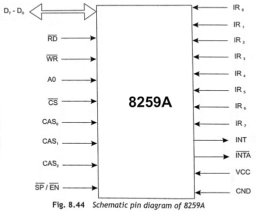
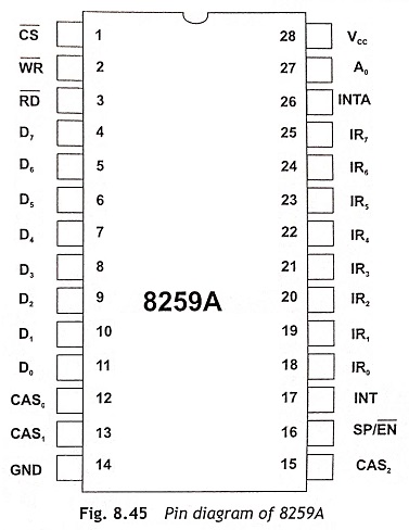
The Intel 8259A programmable Interrupt Controller handles up to eight-vectored priority interrupts for the CPU. This IC is cascadable for up to 64-vectored priority interrupts without additional circuitry. This IC is available in a 28-pin DIP package and uses NMOS technology and requires a single 5 V supply. Circuitry is static, requiring no clock input. The schematic diagram of 8259A Programmable Interrupt Controller is depicted in Fig. 8.44. The pin diagram of 8259A Programmable Interrupt Controller is also shown in Fig. 8.45 and the pin functions are explained below:
VCC 5 V supply.
GND GROUND
C̅S̅ (Chip Select) When the chip select pin is active low, this pin enables read RD and write WR operation between the CPU and the 8259A. INTA functions are independent of C̅S̅.
W̅R̅ (Write) A low on this pin, when C̅S̅ is low, enables the 8259A for write operation. This pin also enables to accept command words from the CPU.
R̅D̅ (Read) When R̅D̅ is active low and C̅S̅ is low, this pin enables the 8259A to release status onto the data bus for the CPU.
D7-D0 (I/O Bidirectional Data Bus) These pins are used as bidirectional data buses. The control, status and interrupt-vector information’s are transferred through this bus.
CAS0-CAS2 (I/O Cascade Lines) A 8279A has only eight interrupts. When the number of interrupts requirement is more, a multiple interrupt controller must be connected in cascade. The CAS lines of a 8259A bus is used to control a multiple 8259A structure. These pins are outputs for a master 8259A and inputs for a slave 8259A.
S̅P̅/E̅N̅ (I/O SlaveProgram/EnableBuffer) This is a dual-function pin. When this IC is used in the buffered mode, it can be used as an output to control buffer transceivers (EN). If this IC is not in the buffered mode, it is used as an-input to designate a master (SP = 1) or slave (SP = 0).
INT (Interrupt) This pin goes high whenever a valid interrupt request is asserted. This pin signal is used to interrupt the CPU. Therefore, it is connected to the CPU’s interrupt pin.
IR0-IR7 (Interrupt Requests) These pins are used as asynchronous inputs. Each pin can be used to receive an interrupt request to the CPU by raising an IR input from low to high. The interrupt pin must be maintained at high level until this is acknowledged (edge-triggered mode), or just by a high level on an IR input (level-triggered mode).
I̅N̅T̅A̅ (Interrupt Acknowledge) This pin becomes high when a valid interrupt request is asserted. This pin is used to enable 8259A interrupt vector data onto the data bus by a sequence of interrupt acknowledge pulses issued by the CPU.
A0 (Address Line) This pin works in conjunction with the C̅S̅, W̅R̅, and R̅D̅ pins. This is also used by the 8259A to read various command words the CPU writes and status the CPU wishes to read. Generally, this is connected to the CPU A0 address line.
Functional Description
The functional block diagram of 8259A Programmable Interrupt Controller is shown in Fig. 8.46. Each functional block has been explained below:
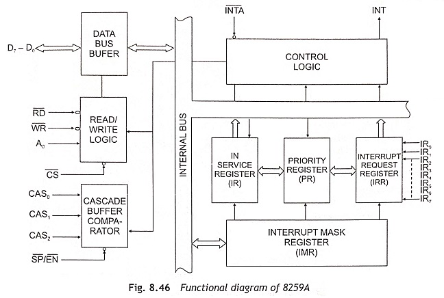
Interrupt Request Register (IRR) The interrupts at the IR input lines are handled by two internal registers, the Interrupt Request Register (IRR) and the In-Service register (ISR). The IRR is used to store all the interrupt requests, which are requesting service and it provides service one by one on the priority basis.
In-Service Register (ISR) The In-Service Register (ISR) is used to store all the interrupt levels which are being serviced, and also keeps a track of the request being served.
Priority Resolver This logic block determines the priorities of the interrupt requests in the IRR. The highest priority is selected and strobed into the corresponding interrupt request of the ISR during INTA pulse.
Interrupt Mask Register (IMR) This Interrupt Mask Register (IMR) stores the bits that mask the interrupt lines to be masked. The IMR operates on the IRR based priority resolver.
Interrupt Control Logic The interrupt control logic block manages the interrupt and the interrupt acknowledge signals. The interrupt (INT) and interrupt acknowledge (INTA) signals are directly send to the CPU interrupt input. The INTA signal from CPU that will cause the 8259A to release vectoring information onto the data bus.
Data Bus Buffer This 3-state, bidirectional 8-bit buffer is used to interface the 8259A to the microprocessor data bus. Control words and status information are transferred through the data bus buffer.
Read/Write Control Logic This block is used to accept Output commands from the CPU. It contains the Initialization Command Word (ICW) registers and Operation Command Word (OCW) registers which store the various control formats for device operation. This function block also allows the status of the 8259A to be transferred onto the data bus.
Cascade Buffer/Comparator The cascade buffer/comparator block stores and compares the IDs of all 8259A’s used in the microprocessor system. The associated three I/O pins (CAS0, CAS1 and CAS2) are outputs when the 8259A is used as a master and are inputs when the 8259A is used as a slave. When the 8259A is used as a master, the 8259A sends the ID of the interrupting slave device onto the CAS0 to CAS2 lines. The slave thus selected will send its preprogrammed subroutine address onto the data bus during the subsequent INTA pulses.
Interrupt Sequence
The most powerful features of 8259A Programmable Interrupt Controller are programmability and the interrupt routine addressing capability. This device allows direct or indirect jumping to the specified interrupt service routine without any polling of the interrupting devices. The interrupt sequence for an interrupt in 8085 microprocessor system has been explained below:
- One or more of the Interrupt Request lines (IR7 to IR0) are raised high, setting the corresponding IRR bits.
- The 8259A Programmable Interrupt Controller evaluates these requests, and sends an INT to the CPU.
- The CPU acknowledges the INT and responds with an INTA pulse.
- After receiving an INTA from the CPU group, the highest priority ISR bit is set, and the corresponding IRR bit is reset. The 8259A will also release a CALL instruction code (11001101) onto the 8-bit data bus through its D7 to D0 pins.
- This CALL instruction will initiate two more INTA pulses to be sent to the 8259A from the CPU group.
- These two INTA pulses allow the 8259A to release its preprogrammed subroutine address onto the data bus. The lower 8-bit address is released at the first INTA pulse and the higher 8-bit address is released at the second INTA pulse.
- This completes the 3-byte CALL instruction released by the 8259A. In the AEOI (automatic end of interrupt) mode, the ISR bit is reset at the end of the third INTA pulse. Otherwise, the ISR bit remains set until an appropriate EOI (end of interrupt) command is issued at the end of the interrupt sequence.
Interfacing of 8259A with 8085
Figure 8.47 shows the interfacing of 8259A with 8085. When the 8259A PIC receives an interrupt, INT becomes active and an interrupt acknowledge cycle is started. If a higher-priority interrupt occurs between the two INTA pulses, the INT line goes inactive immediately after the second INTA pulse. After an unspecified amount of time, the INT line is activated again to signify the higher priority interrupt waiting for service. This inactive time is not specified and can vary between parts. The designer should be aware of this consideration when designing a system that uses the 8259A. It is recommended that proper asynchronous design techniques be followed.
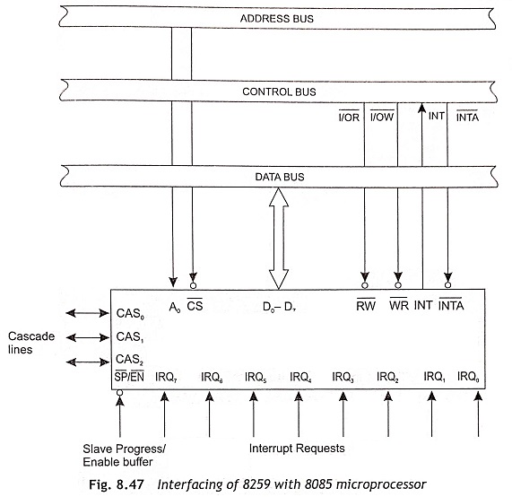
The interfacing steps are explained below:
- The address decoder output is connected with the C̅S̅ input of the IC.
- A0 line is used to select one of the two internal addresses in the device. This is connected to A0 of the address lines of the microprocessor.
- As the device operates in I/O-mapped I/O mode, the R̅D̅ and W̅R̅ signals are connected to I̅O̅R̅ and I̅O̅W̅ signals respectively.
- The interrupt INT pin of 8259A is connected to the INTR input of the 8085 microprocessor.
- INTA output of the processor is connected to the INTA input.
- When S̅P̅ / E̅N̅ pin is high, only one IC is used in the microprocessor-based system. If more than one ICs are connected in cascade, this pin must be low.
- CAS0, CAS1 and CAS2 lines are generally opened.
- There are eight IR input lines (IR0-IR7) are available. When the IR inputs are not used, they must be grounded properly to avoid noise pulse in interrupt lines.
Programming of 8259A Programmable Interrupt Controller
The 8259A accepts two types of command words generated by the microprocessor. These two types of command words are Initialization Command Words (ICWs) and Operation Command Words (OCWs).
Initialization Command Words (ICWs) The 8259A programmable interrupt controller can be initialized by sending a sequence of initialization control words (ICWs) to the controller. There are four initialization control words. The ICW1 and ICW2 always send to 8259 systems. When the system has any slave 8259A in cascade mode, ICW3 must be used. In some special operations such as fully nested mode, ICW4 can be used. All initialization command words are explained below:
Initialization Command Word 1 (ICW1) Whenever a write command is received with A0 = 0 and D4 = 1, it is interpreted by 8259 as Initialization Command Word 1 (ICW1). The ICW1 starts the initialization sequence during which the following automatically occur.
- The edge sense circuit is reset, which means that following initialization, an Interrupt Request (IR) input must make a low-to-high transition to generate an interrupt,
- The Interrupt Mask Register (IMR) is cleared.
- IR7 input is assigned lowest priority 7.
- The slave mode address is set to 7.
- The special mask mode is cleared and status read is set to IRR.
- If IC4 is 0 then all functions selected in ICW4 are set to zero. Master/Slave in ICW4 is only used in the buffered mode.
The format of ICW1 is shown in Fig. 8.48.
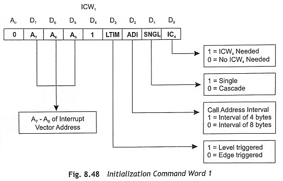
- Bit D0 It indicates whether ICW4 is needed or not. If it is 1, ICW4 is needed and if it is 0, ICW4 is not needed.
- Bit D1 When this bit is 0, then only one 8259 is in the system. If it is 1, the additional 8259A are there in the system.
- Bit D2 ADI stands for address interval. If this bit is ‘0’ then call address interval is 8 and if it is ‘1’ then call address interval becomes 4.
- Bit D3 Bit D3 determines recognition of the interrupts either in level triggered or edge-triggered mode. If this bit is 1 then the input interrupts will be recognized if they are in the level-triggered mode.
- D5-D7 These are A5-A7 bits as shown in Fig. 8.48. For an interval spacing of 4, A0-A4 bits are automatically inserted by 8259A while A0-A5 are inserted automatically for an interval of 8. A5-A7 bits are programmable as set by the bits D5-D7 of ICW1.
Initialization Command Word 2 (ICW2) The Initialization Command Word 2 (ICW2) is shown in Fig. 8.49.
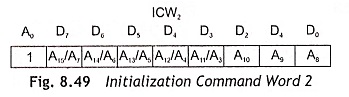
Bits D7-D3 specify address bits A15-A11 interrupt vector address when operating in MCS 80/85 mode.
Bits D2-D0 specify address bits A10-A8 for the interrupt vector address when operating in MCS 80/85 mode. These bits can be set to 0 when working on an 8086 system. T3-T7 are interrupt vector address when the controller operates in 8086/8088 mode.
Initialization Command Word 3 (ICW3) The ICW3 is used only when there is more than one 8259A in the system and cascading is used, in which case SNGL = 0. This will load the 8-bit slave register. The functions of this register are as follows:
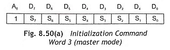
In the master mode (either when SP = 1, or in buffered mode when M/S = 1 in ICW4) a ‘1’ is set for each slave in the system. The master then will release byte 1 of the call sequence (for MCS 80/85 system) and will enable the corresponding slave to release bytes 2 and 3 (for 8086 only byte 2) through the cascade lines.
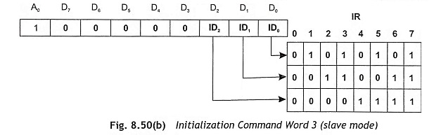
In the slave mode (either when SP = 0, or if BUF = 1 and M/S = 0 in ICW4) bits 2 ± 0 identify the slave. The slave compares its cascade input with these bits and, if they are equal, it releases bytes 2 and 3 of the call sequence for 8086 on the data bus.
S0-S7 = 1 IR input has a slave and S0-S7 = 0 IR -input does not have a slave
Initialization Command Word 4 (ICW4) The format of ICW4 is shown in Fig. 8.51. ICW4 is loaded only if D0 bit of ICW1 (IC4) is set. The position D0-D4 are explained below:
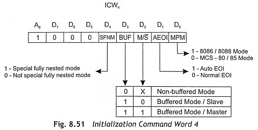
- Bit D0 (MPM) MPM stands for microprocessor mode. MPM = 0 sets the 8259A for MCS-80, 85 system operation, but MPM = 1 sets the 8259A for 8086 system operation
- Bit D1 (AEOI) AEOI stands for the automatic end of interrupt mode. If AEOI = 1, then it is in auto EOI mode and if it is = 0, it is normal EOI mode.
- Bit D2 (M/S) When buffered mode is selected, M/S = 1 means the 8259A is programmed to be a master, and M/S = 0 means the 8259A is programmed to be a slave. If BUF = 0, M/S has no function.
- Bit D3 (BUF) Bit D3 determines buffered/non-buffered mode of operation. If BUF = 1 the buffered mode is programmed. In buffered mode, SP/EN becomes an enable output and the master/ slave determination is by M/S.
- Bit D4 (SFNM) SFNM stands for the Special Fully Nested Mode. If SFNM = 1 then this mode is programmed. In the cascaded mode of operation, when a slave receives a higher priority interrupt request than one, which is already in service (through the same slave), it would not be recognized by the master. This is happening as the master ISR bit is already in the set condition; thereby it ignores all requests of equal or lower priority. Therefore the higher priority interrupt won’t be serviced until the master ISR bit is reset by an EOI command. This is most likely to happen after the completion of the lower priority routine.
If a truly fully nested structure is required within a slave 8259A, the especially fully nested mode should be used. The SFNM is programmed for the master mode only and done during master initialization through ICW4. In this mode, the master will ignore interrupt requests of lower priority, and will respond to requests of equal or higher priority.
The Fully Nested Mode (FNM) is auto set after initialization is over. In this mode all interrupt requests are arranged from highest priority (IR0) to lowest priority (IR7). This mode can also be changed through operation command words (OCWs). When 8259 acknowledges an interrupt request through INTR pin, the device can find out the highest priority and the corresponding bit in the Interrupt Service Register (ISR) is set.
The SFNM is different from FNM and the difference between SFNM and FNM are given below:
- In SFNM, the slave is able to place an interrupt request, which has higher priority than the present interrupt being serviced. The master recognizes the higher-level interrupt and can place this interrupt request to the CPU.
- Before issuing an EOI command to the slave, the software must determine if any other slave interrupts are pending in SFNM. After that it reads its ISR (In Service Register). When the ISR contains all zeros, there is no interrupt from the slave in service and an EOI command can be sent to the master. If the ISR is not all zeros, an EOI command should not be sent to the master. When the master ISR bit is cleared with an EOI command while there are still slave interrupts in service, the lower-priority interrupt may be recognized by the master.
Programming Sequence of 8259
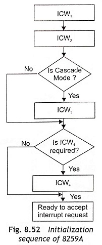
8259 is programmed by issuing initialization of command words and operation command words. Initialization of command words are issued in a sequence. The algorithm for initializing 8259 is given below:
- Write ICW1
- Write ICW2
- If 8259 does not go in the cascade mode of operation, go to Step 5 .
- Write ICW3
- If ICW4 is not required, Go to step 7
- Write ICW4
- Ready to accept interrupt sequence
The algorithm for initialization of 8259A programmable interrupt controller is depicted in Fig. 8.52.
Operation Command Words (OCWs) These are the command words which command the 8259A Programmable Interrupt Controller to operate in various interrupts modes. These operating modes are:
- Fully nested mode
- Rotating priority mode
- Special mask mode
- Polled mode
There are three operation command words such as OCW1, OCW2 and OCW3. These OCWs may be programmed to change the manner in which the interrupts are to be processed. The OCWs can be loaded into the 8259A any time after initialization.
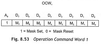
Operation Command Word 1 (OCW1) The format of OCW1 is shown in Fig. 8.53. OCW1 sets and clears the mask bits by programming the Interrupt Mask Register (IMR). M7-M0 represents the eight mask bits. If M = 1, then corresponding interrupt is masked (inhibited) and M = 0 indicates the interrupt is unmasked. A write command with A0 = 1 is interpreted as OCW1, and written after ICW2.
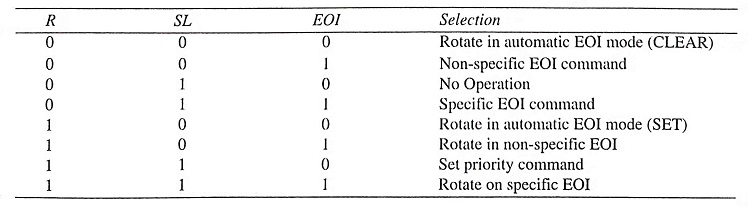
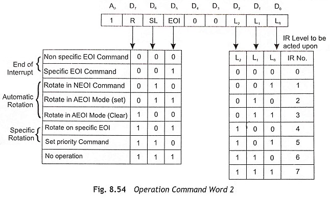
Operation Command Word 2 (OCW2) The OCW2 enables the user to program 8259 in different modes. The format OCW2 is shown in Fig. 8.54. Bits 3 and 4 are always set to 0. L2, L1, L0 bits can be used to set the interrupt level acted upon which the controller must react. R, SL, EOI-these three bits control the rotate and end of interrupt modes and combinations of the two. A chart of these combinations is given below:
The EOI command stands for End Of Interrupt. The interrupt service bit may be reset by an End of Interrupt command. Generally, this command is issued by the CPU just before sending the interrupt service routine. There are two different EOI commands such as non-specific EOI command and specific EOI command.
Non-specific EOI Command The CPU issues a nonspecific EOI command. Actually, this is an OUT instruction by the CPU to 8259A. The 8259A automatically determine the interrupt level, i.e., highest priority interrupt in service and reset the correct bit in the ISR. The nonspecific EOI command must be used when the most recent level acknowledged and serviced is always the highest priority level. On receiving a nonspecific EOI command, 8259A simply resets the highest priority ISR bit, thus confirming to the 8259A that the highest priority routine of the routine in service is finished. The nonspecific EOI command is also known as Fully Nested Mode (FNM). The advantage of the nonspecific EOI command is that IR level specification is not necessary as in the specific EOI Command. But some special consideration must be taken when deciding to use the nonspecific EOI.
Specific EOI Command (SEOI) A SEOI command sent from the microprocessor to 8259A lets it know when a service routine of a particular interrupt level is completed. A SEOI command resets a specific ISR bit and any one of the eight IR levels can be specified. A SEOI command is required when 8259A is unable to determine the IR level. This command is best suited for situations in which priorities of the interrupt levels are changed during an interrupt routine (specific rotation).
Automatic EOI Mode (AEOI) In AEOI mode, no command has to be issued. Therefore, AEOI mode simplifies programming and lower code requirements within interrupt routines.
AEOI mode must be used continuously as the ISR bit of a routine presently in service is reset right after its acknowledgement. Thus it leaves no designation in the ISR that a service routine is being executed. If any interrupt request occurs during this time and interrupts are enabled, it will be serviced regardless of its priority, whether low or high. The problem of ‘over-nesting’ may happen in this case. It occurs when an IR input keeps interrupting its own routine. This results in unnecessary stack pushes, which could fill up the stack in a worst-case condition.
Automatic Rotation—Equal Priority When several communication channels are connected to a microcomputer system, all the channels should be accorded equal priority in sharing information with the microcomputer.
In this method once a peripheral is serviced, all other equal priority peripheral should be given a chance to be serviced before the original peripheral is serviced again. This is accomplished automatically assigning a peripheral the lowest priority after being serviced. In this way the device, presently being serviced, would have to wait until all other devices are serviced.
The automatic rotation is two types:
- Rotate on nonspecific EOI Command
- Rotate on automatic EOI Mode
Rotate on Nonspecific EOI Command When the rotate on NSEOI command is issued, the highest ISR bit is reset. Just after it is reset by a nonspecific EOI command, the corresponding IR level is assigned lowest priority. Figure 8.55 shows how the rotate on nonspecific EOI command effects the interrupt priorities.
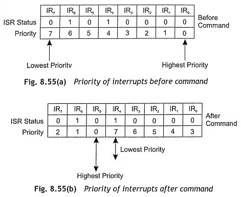
Let us assume that the LR0 has the highest priority and IR7 has the lowest priority before command as shown in Fig. 8.55 (a). It is also assumed that IR6 and IR4 are already in service but neither is completed. As IR4 has the highest priority, IR4 routine be executed. When a NSEOI command is executed, Bit 4 in the ISR is reset. Then IR4 becomes the lowest priority and IR5 becomes the highest priority as depicted in Fig. 8.55 (b).
Rotate in Automatic EOI Mode The rotate in Automatic EOI Mode (AEOI) works like the rotate on nonspecific EOI (NSEOI) command. The difference between NSEOI and AEOI is that priority routine is done automatically after the last I̅N̅T̅A̅ pulse of an interrupt request. To enter or exit from this mode, a rotate-in-automatic EOI set command and rotate-in-automatic EOI clear command are provided.
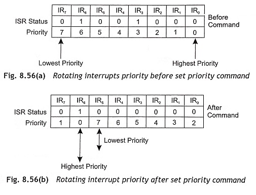
Set Priority Command The set priority command is used to assign an IR level the lowest priority. All other interrupt levels will be in the fully rested mode based on the newly assigned low priority. The relative priorities of the interrupt levels before the set priority command and after the set priority command are depicted in Fig. 8.56(a) and 8.56(b) respectively. As IR3 has the highest priority, IR3 routine be executed next. When the IR3 routine is executing and set priority command is issued to the 8259A, priorities will be changed. Then IR6 is the highest and IR5 as the lowest priority as given in Fig. 8.56 (b).
Rotate on Specific EOI Command The rotate on specific EOI command is the combination of set priority command and specific EOI command. Just like the set priority command, a specified IR level will be assigned lowest priority. Similar to the specific EOI command, a specified level will be reset in the ISR. In this way the rotate on specific EOI command achieves two operations in only one command.
Operation Command Word 3 (OCW3) The OCW3 are used to perform the following operations:
- To read the status of registers (IRR and ISR)
- To set/reset the special mask and polled modes
The format of OCW3 is shown in Fig. 8.57.
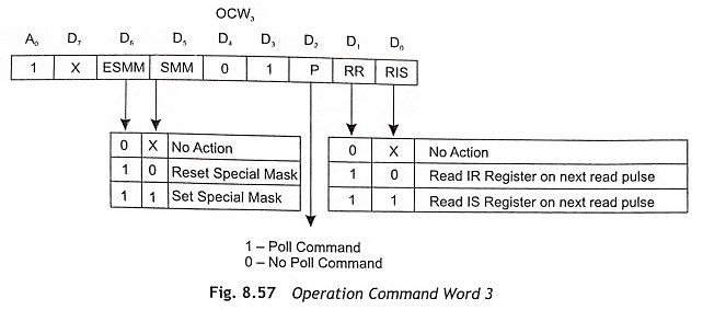
RIS This bit is used to select the In service register (ISR) or the Interrupt Request Register (IRR) and then read register. When RIS = 0 and RR = 1, IRR is selected. If RIS = 1 and RR = 1, ISR is selected.
RR This bit is used to execute the read register command. When RR = 0, the read register command will not issued and no action takes place. If RR = 1, the read register command is issued and the state of RIS decide the register to be read.
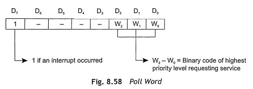
P (Poll Mode) This bit is used for POLL command. When P = 1, the poll command is issued. If P = 0, the poll command is not issued. In this mode, the interrupting devices seeking services from 8085 are polled one after another and to detect which device has sought for interrupt request? In the polled mode (P = 1), 8259A is then read by masking its R̅D̅ and C̅S̅ pins ‘0’. The ISR bit is set corresponding to the highest level interrupt in the IRR. The poll word is shown in Fig. 8.58.
Special Mask Mode (SMM) The special mask mode enables interrupt from all levels except the level currently in service. When SMM = 1, the special mask mode is selected. Once the special mask mode is set, it remains in effect until reset. If SMM = 0, the special mask mode is not selected. The special mask mode can be set when ESSM bit enables SMM (ESSM = 1) in OCW3. The special mask mode can be cleared by loading OCW3 with ESSM = 1 and SMM = 0.
ESMM This bit is used to enable/disable the effect of the special mask mode (SMM). When ESMM = 1, the special mask mode is enabled. If ESMM = 0, the special mask mode is disabled.