8086 Interrupt Types:
The 8086 Interrupt Types are
Dedicated Interrupts:
Type 0 : Divide by Zero Interrupt
When the quotient from either a DIV or IDIV instruction is too large to fit in the result register; 8086 Interrupt Types will automatically execute type 0 interrupt.
Type 1 : Single Step Interrupt
The type 1 interrupt is the single step trap. In the single step mode, system will execute one instruction and wait for further direction from user. Then user can examine the contents of registers and memory locations and if they are correct, user can tell the system to execute the next instruction. This feature is useful for debugging assembly language programs.
An 8086 Interrupt Types system is used in the single step mode by setting the trap flag. If the trap flag is set, the 8086 will automatically execute a type 1 interrupt after execution of each instruction. But the 8086 has no such instruction to directly set or reset the trap flag. These operations can be performed by taking the flag register contents into memory, changing the memory contents so to set or reset trap flag and save the memory contents into flag register.
Assembly language program to set trap flag :
PUSHF ; save the contents of trap flag in stack memory
MOV BP, SP ; copy SP to BP for use as index
OR [ BP + 0 ], 0100H ; set the Bit 8 in the memory pointed by BP i.e. set TF bit
POPF ; Restore the flag register with TF = 1 .
To reset the trap flag we have to reset Bit 8. This can be done by using AND [BP + 0 ], OFEFFH instruction instead of OR [BP + 0], 0100H.
Type 2 : Non Maskable Interrupt
As the name suggests, this interrupt cannot be disabled by any software instruction. This interrupt is activated by low to high transition on 8086 NMI input pin. In response, 8086 will do a type 2 interrupt.
Type 3 : Breakpoint
The type 3 interrupt is used to implement break point function in the system. The type 3 interrupt is produced by execution of the INT 3 instruction. Break point function is often used as a debugging aid in cases where single stepping provides more detail than wanted. When you insert a breakpoint, the system executes the instructions upto the breakpoint, and then goes to the breakpoint procedure. In the break point procedure you can write a program to display register contents, memory contents and other information that is required to debug your program. You can insert as many breakpoints as you want in your program.
Type 4 : Overflow Interrupt
The type 4 interrupt is used to check overflow condition after any signed arithmetic operation in the system. The 8086 Interrupt Types overflow flag, OF, will be represented in the destination register or memory location.
For example, if you add the 8-bit signed number 0111 1000 (+ 120 decimal) and the 8 bit signed number 0110 1010 (t 106 decimal), result is 1110 0010 (- 98 decimal). In signed numbers, MSB (Most significant Bit) is reserved for sign and other bits represent magnitude of the number. In the previous example, after addition of two 8-bit signed numbers result is negative, since it is too large to fit in 7 bits. To detect this condition in the program, you can put interrupt on overflow instruction, INTO, immediately after the arithmetic instruction in the program. If the overflow flag is not set when the 8086 executes the INTO instruction, the instruction will simply function as an NOP (no operation). However, if the overflow flag is set, indicating an overflow error, the 8086 will execute a type 4 interrupt after executing the INTO instruction.
Another way to detect and respond to an overflow error in a program is to put the jump if overflow instruction (JO) immediately after the arithmetic instruction. If the overflow flag is set as a result of arithmetic operation, execution will jump to the address specified in the JO instruction. At this address, you can put an error routine which responds in the way you want to the overflow.
Software Interrupts:
Type 0 – 255 :
The 8086 INT instruction can be used to cause the 8086 to do one of the 256 possible interrupt types. The interrupt type is specified by the number as a part of the instruction. You can use an INT2 instruction to send execution to an NMI interrupt service routine. This allows you to test the NMI routine without needing to apply an external signal to the NMI input of the 8086 Interrupt Types.
With the software interrupts you can call the desired routines from many different programs in a system. e.g. BIOS in IBM PC. The IBM PC has in its ROM collection of routines, each performing some specific function such as reading character from keyboard, writing character to CRT. This collection of routines referred to as Basic Input Output System or BIOS.
The BIOS routines are called with INT instructions. We will summarize interrupt response and how it is serviced by going through following steps.
- 8086 pushes the flag register on the stack.
- It disables the single step and the INTR input by clearing the trap flag and interrupt flag in the flag register.
- It saves the current CS and IP register contents by pushing them on the stack.
- It does an indirect far jump to the start of the routine by loading the new values of CS and IP register from the memory whose address calculated by multiplying 4 to the interrupt type. e.g. If interrupt type is 4 then memory address is 4 x 4 = 1010 = 10H. So 8086 Interrupt Types will read new value of IP from 00010H and CS from 00012H.
- Once these values are loaded in the CS and IP, 8086 will fetch the instruction from the new address which is the starting address of interrupt service routine.
- An IRET instruction at the end of the interrupt service routine gets the previous values of CS and IP by popping the CS and IP from the stack.
- At the end the flag register contents are copied back into flag register by popping the flag register form stack.
INTR Interrupt 0 – 255:
The 8086 INTR input can be used to interrupt a program execution. The 8086 is provided with a maskable handshake interrupt. This interrupt is implemented by using two pins – INTR and INTA. This interrupt can be enabled or disabled by STI (IF=1) or CLI (IF=0), respectively. When the 8086 is reset, the interrupt flag is automatically cleared (IF=0). So after reset INTR is disabled. User has to execute STI instruction to enable INTR interrupt.
The 8086 responds to an INTR interrupt as follows :
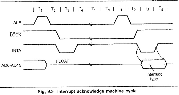
- The 8086 first does two interrupt acknowledge machine cycles as shown in the Fig. 9.3 to get the interrupt type from the external device. In the first interrupt acknowledge machine cycle the 8086 floats the data bus lines AD0-AD15 and sends out an INTA pulse on its INTA output pin. This indicates an interrupt acknowledge cycle in progress and the system is ready’ to accept the interrupt type from the external device. During the second interrupt acknowledge machine cycle the 8086 sends out another pulse on its INTA output pin. In response to this second INTA pulse the external device puts the interrupt type on lower 8 bits of the data bus.
- Once the 8086 receives the interrupt type, it pushes the flag register on the stack, clears TF and IF, and pushes the CS and IP values of the next instruction on the stack.
- The 8086 then gets the new value of IP from the memory address equal to 4 times the interrupt type (number), and CS value from memory address equal to 4 times the interrupt number plus 2.