Interrupt Structure of 8096:
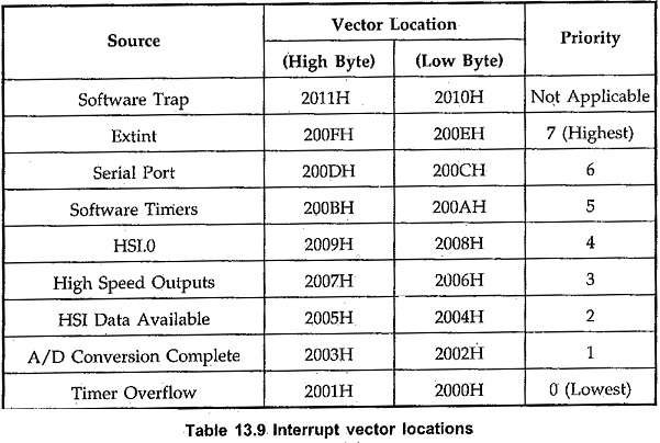
Eight interrupt sources are available on the Interrupt Structure of 8096. When enabled, an interrupt occurring on any of these sources will read the address of interrupt service routine (ISR) from the corresponding vector location and force a call to ISR. Table 13.9 shows the interrupt sources and their respective vector locations.
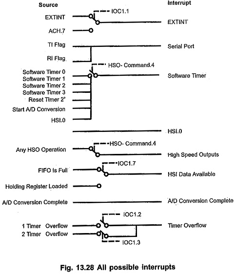
In addition to the 8 standard interrupts, there is a TRAP instruction which acts as a software interrupt. This instruction is not currently supported by the MCS-96 Assembler and is reserved for use by Intel development systems. Many of the interrupt sources can be activated by several methods, Fig. 13.28 shows all of the possible sources for interrupts.
Block Diagram of Interrupt System:
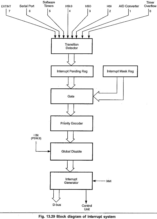
Fig. 13.29 shows block diagram of the interrupt system.
Transition detector:
Transition detector tests each of the interrupt sources for a 0 to 1 transition. If this transition occurs, the corresponding bit in the Interrupt Pending Register (0009H), is set.
Interrupt Pending Register:
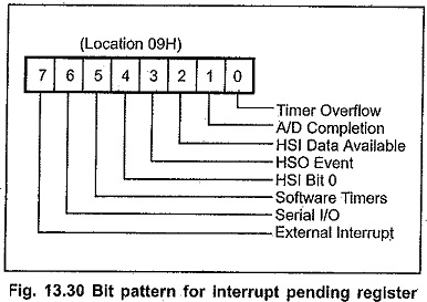
Interrupt Pending Register stores the infomation of activated interrupts by setting the corresponding bits. Bit postions for particular interrupt sources are shown in Fig. 13.30. The bit is cleared when the interrupt routine is called. Since this is read/write register, it is possible to generate software interrupts by setting bits within the register, or remove pending interrupts by clearing the corresponding bits in this register. The pending register can be set even if the interrupt is disabled.
While writing to the pending register it’ is necessary to clear interrupts. If the interrupt has already been acknowledged when the bit is cleared, a 4 state time “partial” interrupt cycle will occur. This is because the Interrupt Structure of 8096 will have to fetch the next instruction of the normal instruction flow, instead of proceeding with the interrupt processing as it was going to. The effect on the program will be essentially that of an extra
Interrupt Mask Register:
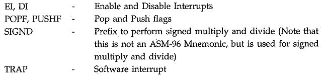
Enabling and disabling of individual interrupts is done through the Interrupt Mask Register, (0008H). If the bit in the mask register is a .1 then the interrupt is enabled; otherwise it is disabled. Even if an interrupt is masked it may still become pending. It may, therefore, be desirable to clear the pending bit before unmasking an interrupt.The Interrupt Mask Register can also be accessed as a lower byte of the PSW so the PUSHF and POPE instructions save and restore the contents of Interrupt Mask Register.
Global Disable:
All of the interrupts may be enabled and disabled simultaneously by using the “EI” (Enable Interrupt) and “DI” (Disable Interrupt) instructions. EI and DI set and clear PSW.9, the interrupt enable bit. They do not affect the contents of the interrupt mask register.
Priority Encoder:
The priority encoder looks at all of the interrupts which are both pending and enabled and selects the one with the highest priority.
Interrupt Generator:
The interrupt generator forces a call to the location in the indicated vector location of the highest priority interrupt. This location is the starting location of the Interrupt Service Routine (ISR).
8096 Interrupt Timing Diagram:
Interrupts are not always acknowledged immediately. The interrupt signal has to occur prior to 4 state-times before the end of an instruction, as shown in Fig 13.31. If it does not occur prior to 4 state-times before the end of an instruction, it will be acknowledged after the execution of the next instruction. This is because an instruction is fetched and prepared for execution a few state times, before it is actually executed.
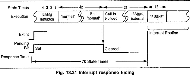
There are 6 instructions which always inhibit interrupts from being acknowledged until after the next instruction has been executed. These instructions are :
When an interrupt is acknowledged, a call is forced to the location indicated by the specified interrupt vector. This call occurs after the completion of the instruction in process, except for few instructions as mentioned above. The procedure of getting the vector and forcing the call requires 21 state times. If the stack is in external RAM an additional 3 state times are required.
The maximum number of state times required from the time an interrupt is generated (not acknowledged) until the Interrupt Structure of 8096 begins executing code at the desired location is the time of the longest instruction, NORML (Normalize – 43 state times), plus the 4 state times prior to the end of the previous instruction, plus the response time (21 to 24 state times). Therefore, the maximum response time is 71 (43 + 4 + 24) state times. This does not include the 12 state times required for PUSHF if it is used as the first instruction in, the interrupt routine or additional latency caused by having the interrupt masked or disabled.