Output Stage of an Op Amp and its Voltage Transfer Characteristics:
The output stage of an op amp is another requirement which should have very small output impedance and provide the external load current so that large output voltage swing is obtained.
The output of an op-amp is the voltage measured at the output of this final stage which is usually a push-pull complementary amplifier, as shown in Fig. 20.64.
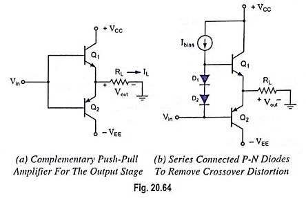
When positive cycle of input voltage Vin arrives, Q1 behaves as current supplier to load RL and Q2 is off.
When negative cycle of Vin arrives, Q1 is off, Q2 acts as a sink to remove current from the load, (it decreases the load current).
But the circuit bears crossover distortion when Vin = 0 (when voltage swings from positive to negative). To reduce this problem of getting Vin = VBE = 0.7 V when it should be zero, we provide a constant dc bias voltage between the two bases so that small current exists in quiescent condition. For this, two diodes D1 and D2 are connected, as shown in Fig. 20.64 (b).
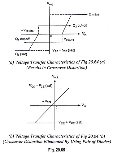
The transfer characteristics shows that if Vin = 0, Vout ≠ 0. Here, Vin is obtained from level shifter, we can have Vout = 0 with Vin = 0 by making quiescent value of Vin = -VBE2.
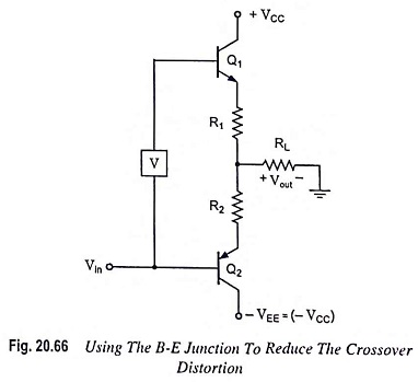
Figure 20.66 can also reduce the crossover distortion. The output voltage is about 1.1 V between two bases. Here both transistors Q1 and Q2 conduct slightly under quiescent condition.