8086 Microprocessor Pin Diagram and 8088 Pin Diagram:
In order to implement many situations in the microcomputer system the 8086 Microprocessor Pin Diagram and 8088 Pin Diagram has been designed to work in two operating modes :
- Minimum Mode Configuration of 8086
- Maximum Mode Configuration of 8086
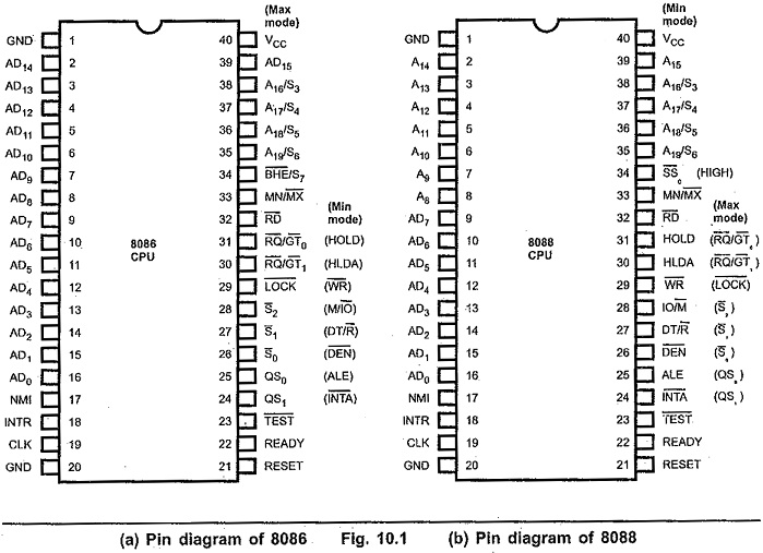
The Minimum Mode Configuration of 8086 is used for a small systems with a single processor and Maximum Mode Configuration of 8086 is for medium size to large systems, which often include two or more processors. Fig. 10.1 shows the 8086 Microprocessor Pin Diagram and 8088 Pin Diagram in minimum as well as maximum mode. As a close comparison reveals, there is no much difference between two microprocessors – both are packaged in 40-pin dual-in-line package (DIPS). As mentioned in chapter 1, the 8086 is a 16-bit microprocessor with a 16-bit data bus, and the 8088 is a 16-bit microprocessor with an 8-bit data bus. The pin-out shows, the 8086 has pin connections AD0-AD15, and the 8088 has pin connections AD0-AD7. There is one more minor difference in one of the control signals. The 8086 has an M/IO pin, and the 8088 has an 10/M pin. The only hardware difference appears on pin 34 of both chips : on the 8086 it is a BHE/S7 pin, while on the 8088 it is a SS0 pin.
Minimum Mode of 8086:
1.AD15-AD0 : Acts as address bus during the first part of machine cycle and data bus for the remaining part of the machine cycle.
2.A19/S6-A16/S3 : During the first part of machine cycle these are used to output upper 4-bits of address. During remaining part of the machine cycle these are used to output status, which indicates the type of operation to be performed in that cycle. S3 and S4 indicate the segment register being used as follows :
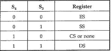
S5 gives the current setting of the interrupt flag (IF) and S6 is always zero.
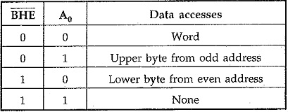
3.BHE/S7 : BHE (Bus High Enable) : Low on this pin during first part of the machine cycle, indicates that at least one byte of the current transfer is to be made on higher order byte AD15-AD8; otherwise the transfer is made on lower order byte AD7-AD0.
Status S7 is output during the later part of the machine cycle, but, presently, 57 has not been assigned a meaning.
4.NMI : It is a positive edge triggered nortmaskable interrupt request,
5.INTR : It is a level triggered maskable interrupt request. It is sampled during the last clock cycle of each instruction to determine if the processor should enter into an interrupt service routine.
6.CLK : 8086 requires clock signal (with 33 % duty cycle) from some external, crystal controlled generator to synchronize internal operations. Clock frequency depends
7.RESET : It clears PSW, IP, DS, SS, ES, and the instruction queue. It then sets CS to FITIMI. This signal must be high for at least 4 clock cycles. When RESET is removed, 8086 will fetch its next instruction from physical address FEFFOH.
8.READY : If this signal is low the 8086 enters into wait state. This signal is used primarily to synchronize slower peripherals with the microprocessor.
9.TEST (Input) : This signal is only used by the WAIT instruction. The 8086 enters into a wait state after execution of the WAIT instruction until a LOW signal on the TEST pin. TEST signal is synchronized internally during each clock cycle on the leading edge of the clock cycle.
10.RD (Output) : RD is low whenever the 8086 is reading data from memory or an I/O device.
11. MN/MX (Input) : The 8086 can be configured in either minimum mode or maximum mode using this pin. This pin is tied high for minimum mode.