Three Phase AC Voltage Controller:
To control the current and voltage of three phase loads, Three Phase AC Voltage Controller are required. The single phase controller described previously can be introduced singly in each phase or line, to form a three phase controller. There exist a variety of connections for Three Phase AC Voltage Controller.
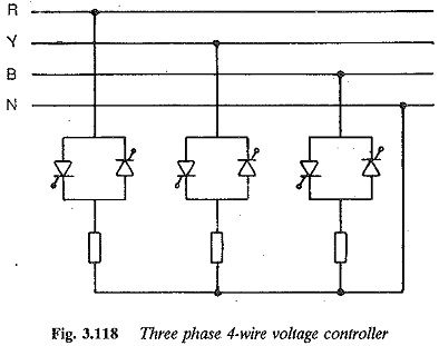
A three phase four wire controller is shown in Fig. 3.118. The load neutral and supply neutral are connected together. Each of the three controllers can be independently controlled to feed the load impedance. Each phase has the same relations as a single phase controller. The analysis is simple and straightforward since the system can be studied as if the loads here are supplied individually by single phase controllers. The neutral and line currents contain triplet harmonics along with other odd harmonics.
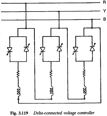
A similar connection, which can function as three groups of single phase controllers, is shown in Fig. 3.119. In this connection, three single phase converters supplying their loads are connected in delta. Each controller supplies its own load. Unlike the previous four wire star-connection, the triplen harmonics are absent here. The other odd harmonics are present.
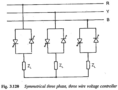
There are certain types of connections which are difficult to analyse. One such circuit is a three phase, three wire star-connected controller, which is normally used when the source neutral cannot be loaded or is absent. The load neutral is isolated. The circuit is depicted in Fig. 3.120. The system is complicated and has to be studied and analysed as a three phase circuit.
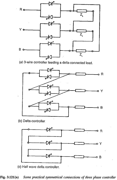
Several other possible connections of Three Phase AC Voltage Controller are depicted in Fig. 3.121. All of them have to be studied as three phase circuits. The operation of a Three Phase AC Voltage Controller is affected by both the load and the type of connections of the single phase controllers used to form the three phase unit. The analysis also differs for each configuration. It is difficult to summarise the features of each circuit.
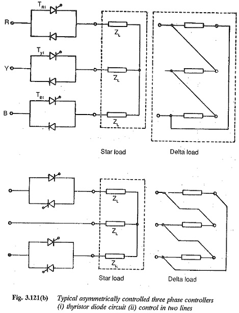
A Three Phase AC Voltage Controller has symmetrical control if both the back to back connected thyristors have the same firing angle. It has asymmetrical control if the firing angles differ or if one of the thyristors is replaced by a diode, or if the controllers are placed in only two of the three lines.
We now discuss the features of a symmetrically controlled three phase, three wire, star-connected controller for both ohmic and inductive loads. The voltage and current waveforms and control characteristics are derived.
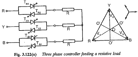
The schematic of a three phase, three wire voltage controller feeding a three phase, star-connected balanced resistance is shown in Fig. 3.122. Phase control of the thyristors is employed. The phase and line voltages of the three phase system are shown in Fig. 3.122. For a controller, the control pulse is of a long duration, equal to the conduction period of the thyristor. This is to make sure that the firing pulse is available at the gate whenever the thyristor is forward biased, so that the thyristor can go into conduction. It also ensures the firing of the thyristor whenever a forward current is expected. If, because of some circuit condition, the current goes to zero the thyristor turns off. A lengthy pulse can bring it into conduction. Further, slow building up of current in the load circuit when the thyristor is fired (to give maximum load voltage) may cause the thyristor to go to an off state if it is not fully turned on.
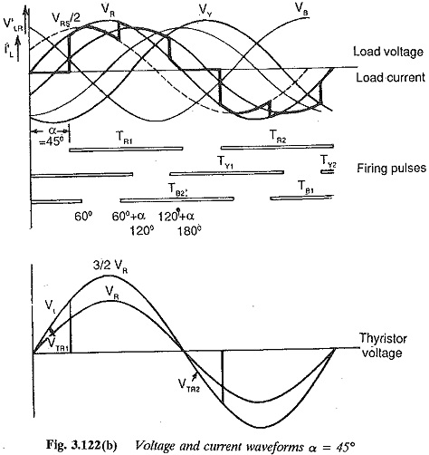
In cases of inductive loads, the current zero occurs after the voltage zero and hence a trigger pulse must be present continuously, so that the thyristor turns on at the desired instant when the forward voltage occurs. However, when long gate pulses or a train of pulses are applied to the thyristor to ensure the conduction whenever the voltage is positive to the leakage currents during reverse bias of the thyristor must be acceptable. Further, the operation may be upset by the voltage sharing of the series-connected thyristors. The angle is reckoned from the zero of the voltage. The conduction period for the thyristor for ohmic load is 180° and the firing pulse occurs for 180°.
The voltage across the load impedance can be determined as follows:
1. When a controller is in the non-conducting state the corresponding phase voltage of the load is zero assuming a star connected load.
2. If two controllers conduct the voltage of the conducting phases is half the line voltage between which the conducting controllers are placed.
3. If all the there controllers are conducting the load is effectively a three phase load supplied from a three phase balanced source. So, the load voltages can be determined using three phase circuit analysis. For balanced load the load phase voltage is same as source phase voltage.
4. Only one converter receives firing pulse with no other converter being in the conducting state, no conduction takes place. All the phase voltages are zero.