Internal Architecture of 8275 CRT Controller:
The 8275 programmable CRT controller is a single-chip device that generates all the signals which are used for interfacing a microprocessor system. The main function of the 8275 CRT controller is to refresh the display by buffering the information from the main memory. This is also used to keep track of the current display position of the screen. This device has the following features:
- Programmable screen and character format
- Six independent visual field attributes
- Eleven visual character attributes
- Four types of cursor control
- Light pen detection and registers
- Duel row buffer
- Programmable DMA burst mode
Functional Description of 8275 CRT Controller
Figure 9.36 shows the internal architecture of the 8275 CRT controller and its functional description of each block have been explained below:
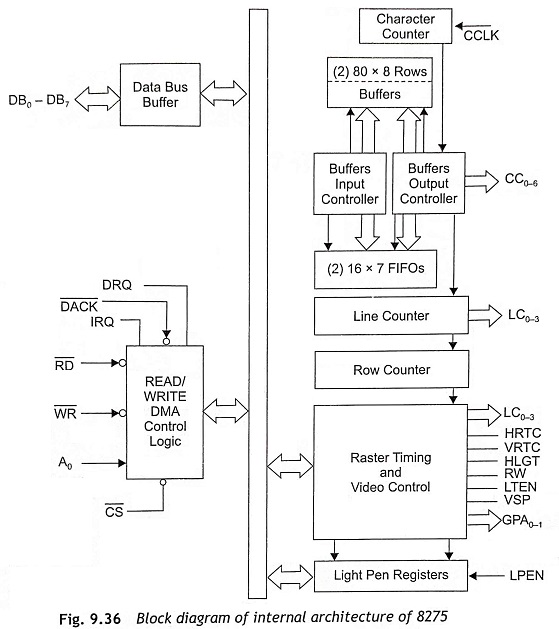
Data Bus Buffer This tri-state bi-directional 8-bit buffer is used to interface the 8275 with the system data bus. The data bus buffer accepts inputs from the system control bus and generates control signals for overall device operation. It consists of the command, parameter and status registers. This bus is also used to read or write the internal registers of 8275 CRT controller.
R̅D̅ (Read) When R̅D̅ is active low; the CPU can read data or status information from the 8275.
W̅R̅ (Write) If W̅R̅ is active low, the CPU can write data or control words to the 8275.
DRQ (DMA Request) When the DRQ output pin is high, the 8275 desires a DMA transfer.
D̅E̅C̅K̅ (DMA Acknowledge) The active low input on D̅E̅C̅K̅ pins informs the 8275 that a DMA cycle is in progress.
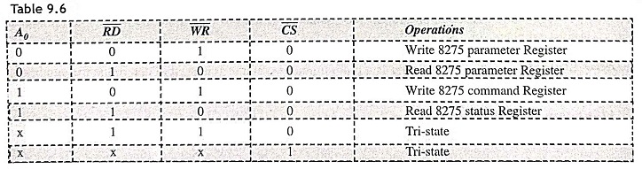
IRQ (Interrupt Request) When the IRQ output pin is high, it informs the CPU that 8275 desires interrupt service. The operation of read/write/DMA control logic function is given in Table 9.6.
Character Counter The character counter is a programmable counter. It is used to determine the number of characters to be displayed per row and the length of the horizontal retrace interval. This is driven by CCLK (Character Clock) input.
Line Counter This is a programmable counter. It is used to determine the number of horizontal lines (sweeps) per character row.
Row Counter The row counter is a programmable counter. It is used to determine the number of character rows to be displayed per frame and the length of vertical retrace interval.
Light Pen Registers The light pen registers consists of two registers that can store the contents of the character counter and row counter whenever a rising edge is detected at the LPEN input pin.
Raster Timing and Video Control The raster timing circuit controls the timing of the Horizontal Retrace (HRTC) and Vertical Retrace (VRTC) outputs. The video control circuit generates LA0-LA1 (Line Attribute), HGLT (Highlight), RVV (Reserve Video), LTEN (Light Enable), VSP (Video Suppress) and GPA0-GPA1 (General Purpose Attribute) output signals.
Row Buffers The row buffers have two 80 character buffers. These buffers are filled from the microcomputer system memory with the character codes to be displayed. When a row buffer is displaying a row of characters, the other is being filled with the next row of characters to be displayed later.
FIFOs There are two sixteen-character FIFOs in the 8275 CRT controller. FIFOs are used to provide extra row buffer length in the transparent attribute mode.
Buffer Input/Output Controllers The buffer input/output controllers are used to decode the character information being placed in the row buffers. When the character is a character attribute, field attribute or a special code, these controllers decide the appropriate action.
Pin Descriptions of 8275 CRT Controller
The pin diagram of 8275 CRT controller is shown in Fig. 9.37 and the function of each pin is explained in this section:
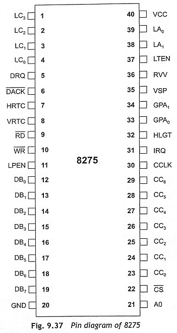
Line Counter, LC3–LC0 (Output) These are the output signals of the line counter which is used to address the character generator for the current line position on the screen.
DMA Request, DRQ (Output) This output signal is used to request the 8257 DMA controller for a DMA operation.
DMA Acknowledge, DACK (Input) The D̅A̅C̅K̅ input signal is used to acknowledge that the requested DMA cycle has been accepted.
Horizontal Retrace, HRTC (Output) The HRTC output signal is active during the programmed horizontal retrace interval. During the active HRTC, the VSP is high and the LTEN is low.
Vertical Retrace, VRTC (Output) The VRTC output signal is active during the programmed vertical retrace interval. During this period, the VSP is high and the LTEN is low.
R̅D̅, Read (Input) This R̅D̅ is a control signal to read the internal registers of 8275.
W̅R̅ Write (Input) The W̅R̅ input control signal is used to write commands into the control registers of 8275 or to write data into the row buffers during a DMA cycle.
Light Pen, LPEN (Input) This is an input signal from the CRT controller which informs the 8275 that a light pen signal has been detected.
Data Bus, DB7-DB0 (Input/Output) The DB7-DB0 lines are bidirectional tri-state data buses that are used for read or write operations from/to the 8275 internal registers.
Video Suppression, VSP, (Output) This output signal is used to blank the video signal to the CRT. This signal is active high,
- During the horizontal and vertical retrace intervals,
- At the top and bottom lines of rows, if an underline is programmed to be at line number 8 or greater than 8
- When an end-of-screen or an end-of-row is detected
- When DMA under-run occurs
- At regular intervals to create blinking displays if specified by the cursor character attribute or field attributes programmed
Reverse Video, RVV (Output) This output signal is used to indicate the CRT circuit to reverse the video signal. This is active at the cursor positions, when a reverse video block cursor is programmed.
Light Enable, LTEN (Output) The LTEN output signal is used to enable the video signal to CRT. This output is active at the programmed underline cursor position and at the position specified by the attribute codes.
A0 Port Address (Input) The input address line is A0. When this pin is high, it selects the ‘C’ port or the command register is selected and if it is low, the `P’ port or the parameter register of 8275 will be selected.
Character Code, CC6-CC0 (Output) These are output lines from the row buffers used for character selection from the character generator.
CS, Chip Select (Input) The read and write operations are enabled by CS.
Character Clock, CCLK (Input) This is a clock input terminal that is driven by the dot/timing logic.
Interrupt Request, IRQ (Output) The IRQ output pin is used to generate an interrupt request to the CPU.
Highlight, HLGT (Output) This output signal is used to intensify the display at the particular positions on the screen as specified by the character attribute codes or the field attributes codes.
General-Purpose Attribute Codes, GPA1-GPA0 (Output) These output signals are enabled by the general-purpose field attribute codes.
Line Attribute Codes LA1-LA0 (Output) These line attribute codes have to be decoded externally by the dot/timing logic to generate the horizontal and vertical line combinations for the graphic displays as specified by the character attribute codes.
Vcc This pin connected with +5 V power supply.
Ground (GND) The ground pin of 8257 is connected to power supply ground terminal.
System Operation
Figure 9.38 shows the interfacing of the 8275 CRT controller with an 8257 DMA controller. The 8275 CRT controller operates with an 8257 DMA controller and the standard character generator ROM for dot matrix decoding in a microprocessor based system. The dot-level timing signals are provided by an external circuit.
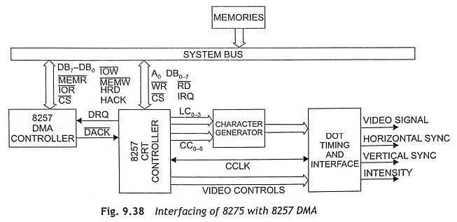
The 8257 is programmable to a large number of display formats. This controller provides raster timing, display row buffering, visual attributes decoding, cursor timing and light pen detection. Initially, the 8275 picks up a row of characters to be displayed from the system memory and load terms into an 80-character row buffer. When one of the two buffers is filled up with characters, the other buffer is on display. In this way, the two row buffers are used to display one by one till the complete display is over.
The number of characters per row and the number of rows per display frame are programmable. While one buffer is being displayed and the other is busy in already displayed then the 8275 CRT controller sends a request for a DMA cycle to fill the already displayed buffer. This process will continue till the complete display frame is over.
The 8275 displays characters rows one line at a time as shown in Fig. 9.39. The 8275 controls the raster timing. This is possible by generating, horizontal retrace (HRTC) and vertical retrace (VRTC) signals. The timing of these signals is also programmable. The 8275 generates a cursor and location of cursor is programmable.