Internal Architecture of 80386 Microprocessor:
The simplified block diagram of the 80386 processor is depicted in Fig. 11.31 and Fig. 11.32 shows the detailed architecture of 80386. The internal architecture of the 80386 processor consists of three different sections such as Central Processing Unit (CPU ), Memory Management Unit (MMU) and Bus Interface Unit (BIU).
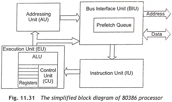
Central Processing Unit (CPU) The central processing unit consists of an Execution Unit (EU) and an Instruction Unit (IU). The Execution Unit EU has eight general-purpose registers and eight special-purpose registers. These registers are used for handling data or calculating offset addresses. The Instruction Unit (IU) is used to decode the opcode bytes received from the 16-byte instruction code queue and followed by arranging them into a 3-instruction decoded-instruction queue. After decoding opcode bytes of instructions, information passes to the control section to provide the necessary control signals. The barrel shifter increases the speed of all shifts and rotate operations. The multiply or divide logic implements the bit-shift-rotate algorithms to complete the instruction operations within minimum time. The 32-bit multiplications/divisions can also be executed within one microsecond by the multiply/divide logic.
Memory Management Unit (MMU) The Memory Management Unit (MMU) has a Segmentation Unit (SU) and a Paging Unit (PU).
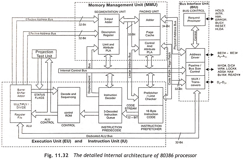
Segmentation Unit (SU) The segmentation unit uses two address components, namely, segment and offset to relocate and sharing of code and data. The segmentation unit allows a maximum size of 4 GB segments. The segmentation unit has four-level protection mechanisms to protect and isolate the system’s code and data from the application programs. The ‘limit and attribute PLA’ is used to check segment limits and attributes at segment level to keep away from invalid accesses to code and data.
Paging Unit (PU) The paging unit arranges the physical memory in terms of pages of 4 KB size each. The paging unit always acts under the control of the segmentation unit and each segment is divided into pages. The virtual memory is also arranged in terms of segments and pages by the memory management unit. Usually, the paging unit converts linear addresses ink) physical addresses. The ‘control and attribute PLA’ is used to check the privileges at the page level. Each page always maintains the paging information of the task.
Bus Interface Unit (BIU) The bus interface unit interfaces the 80386 processor with memory and I/O devices. To fetch instructions and transfer data from code fetcher unit, the processor provides address, data and control signals through BIU. The code prefetch is used for fetching instructions from the memory while BIU is not executing any bus cycle. The bus control section has a ‘request prioritizer’ to decide the priority of the various bus requests. This section controls the bus access. The address driver is used for bus enable signals BE3-BE0 and address signals A31-A0. The pipeline and bus size control units handle the related control signals.