Operating Modes of 80386 Microprocessor:
The Operating Modes of 80386 Microprocessor are given below:
- Real addressing mode,
- Protected mode, and
- Virtual 386 mode.
In this section, the above three modes are explained elaborately.
Real addressing mode
The 80386 always starts from the memory location FFFFFFF0H in the real address mode whenever the processor is reset. In this Operating Modes of 80386, 80386 works as 8086 processor with 32-bit registers and data types. The addressing modes, memory size, interrupt handling of 80386 are same as the real address mode of 80286. Initially, the 80386 starts with real mode and then prepares for protected mode operation. All the instructions of 80386 are available in this mode except protected address mode instructions. In this Operating Modes of 80386, the operand size is 16 bits by default. The 32-bit operands and addressing modes can he used with the help of override prefixes. In this mode, the segment size is 64 k.
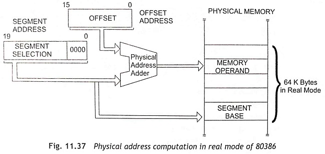
During real addressing mode, the 80386 can address up to 1 MB of physical memory using address lines A19-A0. In this address mode, the paging unit is disabled so that the real addresses are the same as the physical addresses. To compute a physical memory address, the contents of the segment register are shifted left by four bit positions and then added to the 16-bit offset address formed using one of the addressing modes just like the 8086 real address mode. Figure 11.37 shows the physical address computation in real mode of 80386. In real-mode operation of 80386, the segments can be read, written or executed. The segments in 80386 real modes can be overlapped or non-overlapped.
Protected Mode Addressing
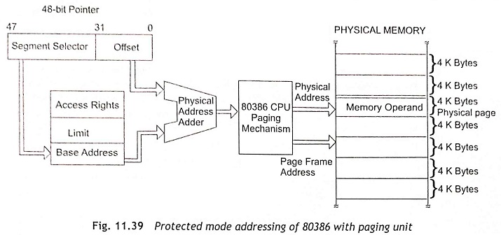
In protected mode, the 80386 can able to address 4 gigabytes of physical memory and 64 terrabytes of virtual memory. In this Operating Modes of 80386, the 80386 has capability to support all programs written for 80286 and 8086 and to be executed. The controls of memory management and protection abilities of 80386 are possible in this Operating Modes of 80386. All additional instructions and addressing modes of 80386 feasible in protected mode.
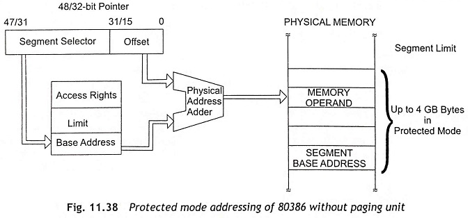
In protected mode addressing, the contents of segment registers are used as selectors which can address the segment descriptors. The segment descriptors consist of the segment limit, base address and access rights byte of the segment. The effective or offset address is added with segment base address to determine linear address. When the paging unit is disabled, the linear address is used as physical address. If the paging unit becomes enabled, the paging unit converts the linear address into physical address. Figure 11.38 and Fig. 11.39 show the protected mode addressing without paging and with paging unit respectively. In general, the paging unit is a memory management unit which is enabled only in the protected mode. The paging mechanism is able to handle memory segments in terms of pages of 4 KB size. Usually, a paging unit operates under the control of segmentation unit.
The 80386 starts with real mode and then changes the operation from real mode to the protected mode operation. To change the operation from real mode to the protected mode, the following steps must be followed:
Step 1 Initialize the IDT so that it contains valid interrupt gates for at least the first 32 interrupt type numbers. Usually, IDT contains up to 256 8-byte interrupt gates to define all 256 interrupt type.
Step 2 Initialize the GDT so that it contains a null descriptor at Descriptor 0. The valid descriptors are used for at least one code, one stack and one data segment.
Step 3 Switch to protected mode after setting the PE bit in CR0.
Step 4 Perform an intrasegment near JMP operation to flush the internal instruction queue and load the TR with the base TSS descriptor.
Step 5 After that, load all the segment registers with their initial selector values.
Step 6 80386 operates in the protected mode using segment descriptors that are defined in GDT and IDT.
Memory Management
The function of the memory-management unit is to convert a linear address into physical address. This unit uses paging mechanism to locate any physical address on memory.
Segmentation The segmentation provides protection to different types of data and code. The 80386 has three types of segment descriptor tables as already exist in the 80286. But, there are some differences between the 80386 and the 80286 segment descriptor structures. The three types of the 80386 segment descriptor tables are given below:
- Global Descriptor Table (GDT)
- Local Descriptor Table (LDT)
- Interrupt Descriptor Table (IDT)
The registers used for descriptor tables GDT, LDT, and IDT are Global Descriptor Table register (GDTR), Local Descriptor Table Register (LDTR ) and Interrupt Descriptor Table register (IDTR) respectively. LGDT, LLDT and LIDT instructions are used to load the three corresponding registers.
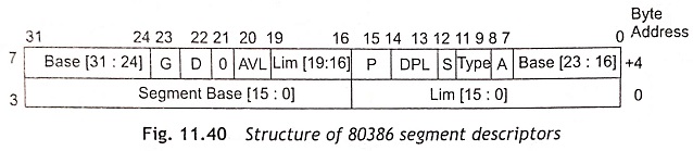
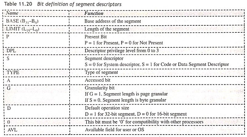
Descriptors The descriptors of 80386 are a series of 8 bytes which is used to describe and locate a memory segment. Figure 11.40 shows the structure of the 80386 descriptor. The 80386 segment descriptors have a 20-bit segment limit and a 32-bit segment address. The descriptors of 80386 contain access right or attribute bits along with the base and limit of the segments. The function of bits of segment descriptors is given in Table 11.20.
The 80386 processor has five types of descriptors as follows:
- Code or data segment descriptors
- System descriptors
- Local descriptors
- TSS (Task State segment) descriptors
- GATE descriptors
The structures of the above descriptors are slightly different from the general segment descriptor structure of 80286. The 80386 also provides a four-level protection mechanism which is exactly in the same way as the 80286 works.
Paging
Paging Operation The paging technique is most commonly used in the memory management of 80386. The segmentation can divide the physical memory into different sizes of segments while the Paging divides the memory into fixed-size pages. Generally, the segments may be the logical segments of the program, but the pages do not have any logical relation with the program. Actually, the fixed size portions of the program module are called pages. The main advantage of the paging system is that it is not required in the complete segment of a task in the physical memory at any time. But only some required pages of the segments should he available in the physical memory for the execution. Subsequently, the memory requirement for the specified task has been reduced, and the CPU can relinquish the available memory for other tasks. When the remaining pages of the specified task are required for execution, these pages can be fetched from the secondary memory storage devices. After execution of pages, it is not required to make available the already executed pages in the memory. Therefore, the space occupied by the already executed pages may be relinquished for other tasks. In this way the paging technique can be used to manage the physical memory for multitasking operating systems. Figure 11.41 shows the complete paging mechanism.
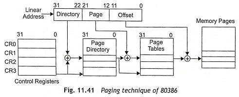
Paging Unit The paging unit of 80386 has a two-level table mechanism to convert the linear address into a physical address. Firstly, the paging unit generates the linear addresses from the segmentation unit then converts the linear addresses into physical addresses. After that, the paging unit converts the complete memory map of a task into pages and the size of each page is 212 or 4 k. Actually, the paging unit handles each task based on page directory, page tables and the page descriptor base registers.
Page Descriptor Base Register The 32-bit linear address is stored at the control register CR2 at which the previous page fault can be detected. The control register CR3 is used as page directory which is known as physical base address register. Hence, CR3 is used to store the physical starting address of the page directory. The lower 12 bits of CR3 must be zero so that page size must be 4K and the page size must be aligned with the directory.
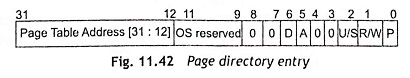
Page Directory The size of the page directory is 4 Kbytes. Each directory entry consists of four bytes. Consequently, a total of 1K or 1024 entries are allowed in a directory. The example of a typical directory entry is shown in Fig. 11.42. The upper 10 bits of the linear address are used as an index to the equivalent page directory entry. The corresponding page directory entry is used to indicate the page tables.
Page Table The size of each page table is 4 Kbytes and each page table has a maximum 1024 entries, Usually, the page table entries contain the starting address of the page and the information about the page. Figure 11.43 shows the page table entry. Generally, the upper 20 bits of the page frame address of the page table entry is combined with the lower 12 bits of the linear address. The address bits A21-A12 of linear address are used to choose the 1024 page table entries.
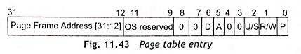
P-bit The P-bit can be used in address translation. When P = 1, the entry can be used in address translation. If P = 0, the entry cannot be used. The P-bit of the presently executed page is always high.
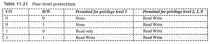
U/S and R/W Bit The User/Supervisor (U/S) bit and Read/Write (R/W) bit are used to provide the four level protections as shown in Table 11.21. The level 0 has the highest privilege level, but the level 3 has the lowest privilege level.
A-bit The A-bit (access bit) must be set by the 80386 processor before accessing any page. If A = 1, the page is accessed. When A=0, the page is not accessed.
D-bit The D-bit (Dirty bit) is set before a write operation to the page. The D-bit is undefined for page directory entries.
The OS reserved bits are defined by the operating system.
Conversion of Linear Address to Physical Address
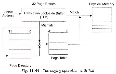
Initially the paging unit gets a 32-bit linear address from the segmentation unit. Then the upper 20 bits of the linear address (A31-A12) are compared with the 32 entries in the translation look-aside buffer to find if any matches exist with the 32 entries. Whenever it matches, the 32-bit physical address is computed from the matching TLB entry and put on the address bus.
During the linear-addresses-to-physical-addresses conversion, each conversion process uses the two-level paging and a certain amount of time is always wasted in the conversion process. To optimize conversion process, a 32 entry or 32 x 4 bytes page table cache is used. This page table cache stores the just now accessed 32-page table entries. The page table cache is also called Translation Look-aside Buffer (TLB). When a linear address is converted to a physical address, firstly check the page table cache entries to find the corresponding address. Figure 11.44 shows the paging operation with TLB.
If the page table entry does not exist in TLB, the 80386 processor reads the page directory entry. After that it checks the P-bit of the directory entry. When P = 1, the page table exists in the memory. Subsequently, 80386 uses the appropriate page table entry and sets the A bit (access bit). If P = 1 in the page table entry, it is confirmed that the page is available in the memory. After that the 80386 processor updates the A and D bits and accesses the page. Then upper 20 bits of the linear address will be read from the page table and will be stored in TLB for future access. If P = 0, the processor generates a page fault exception to indicate that page protection rules are violated.
Virtual 8086 Mode
In real mode, 80386 is able to execute the 8086 programs along with all capabilities of 80386. But once the 80386 processor enters into the protected mode from real mode, it cannot revert back to the real mode without a reset operation. During the protected mode of operation, 80386 processors confer a virtual 8086 operating environment to execute the application programs of 8086. Therefore, the virtual mode operation of 80386 provides an advantage of executing 8086 programs although the 80386 processor is in protected mode.
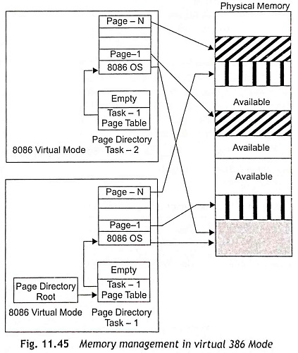
The address computation mechanism in virtual 80386 modes is same as 8086 real mode. In this Operating Modes of 80386, 80386 can address 1 Mbytes of physical memory, which will be within the 4 Gbytes memory address of the protected mode of 80386. The paging mechanism and protection capabilities are also available in this mode of operation. In the virtual mode, the paging unit provides 256 pages, each of 4 Kbytes size. Each of the pages will be anywhere within the maximum 4 Gbytes physical memory. The 80386 can support multiprogramming; hence the multiple 8086 real-mode software applications can be executed at a time. Figure 11.45 shows the memory management in virtual 386 modes in a multitasking virtual 8086 environment.