Register Architecture of 68000 Microprocessor:
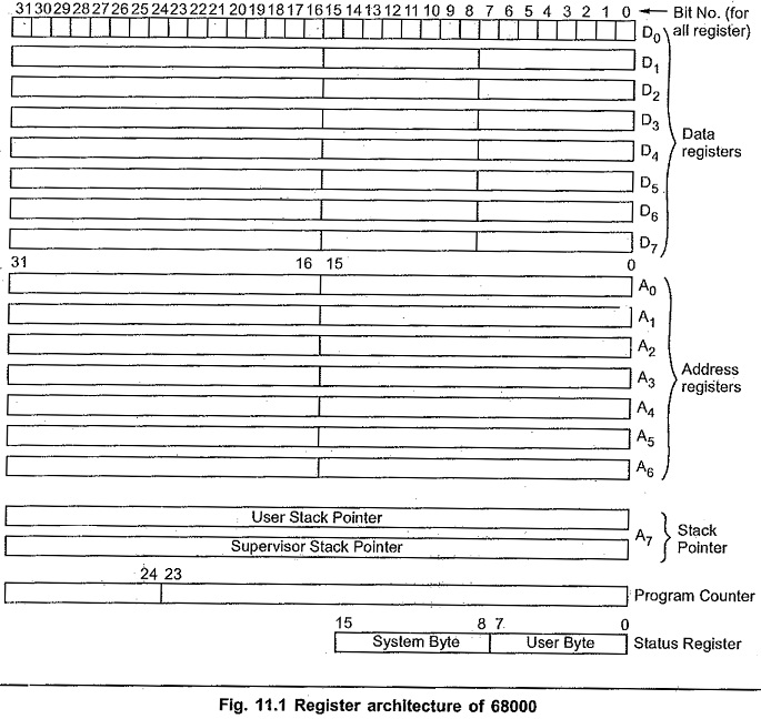
Fig. 11.1 illustrate the Register Architecture of 68000 Microprocessor.
Data Registers:
The data registers can be used to handle (8-bit) bytes, (16-bit) words, or 32-bit long words. When a data register is used as a source or destination operand, only the appropriate low-order portion of the Register Architecture of 68000 Microprocessor will be altered by the specified operation; the most significant bits will be unaffected..
Address Registers:
There are seven general purpose address registers (A0-A6). These registers can handle either 16-bit word or 32-bit long word operands.
Status Registers:
A 16-bit status register is divided into two 8-bit bytes : The system byte and the user byte. Fig. 11.2 shows the bit assignments for the status register. The system byte of the status register contains status information that is system-related. The user byte, on the other hand, contains the condition code status bits (X, N, Z, V and C) which are instruction or program related. Bits in the system byte of the Status register can only be altered when the MC 68000 is in the supervisor mode.
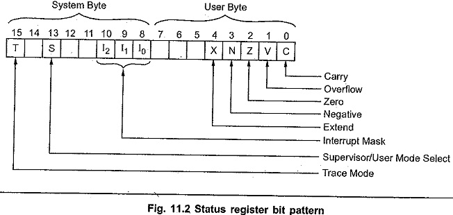
The Carry (C) bit is set if there is a carry out of the most significant bit following an addition operation, or if a borrow is required from the most significant bit during a subtraction. This status bit is also modified by certain shift and rotate instructions.
The Overflow (V) bit is the exclusive-OR of the carries out of the most significant and next higher-order bits of the operand following arithmetic operations. The setting of the overflow bit signifies a magnitude overflow since the result cannot be represented in the specified operand size.
The Zero (Z) bit is set whenever the result of an operation is zero; it is reset otherwise.
The Negative (N) bit is the equivalent of the sign status bit provided in most of the microprocessors. The negative bit is equal to the value of the most significant result bit following arithmetic operations. If a signed binary arithmetic operation is being performed, a negative status of 0 specifies a positive or zero result, whereas a Negative status of 1 specifies a negative result.
The Extend (X) bit is used in multiprecision arithmetic operations. When it is affected by an instruction, it is set to the same state as the carry bit.
The three most significant bits (bits 5, 6 and 7) of the user byte of the status register are not currently assigned and will always be zero.
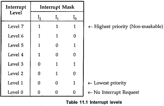
The three least significant bits (bits 8, 9 and 10) of the Status register’s System byte form the interrupt mask. The MC68000 provides seven levels of interrupts. The level of any given interrupt is decoded from the three interrupt pins. The interrupt priorities are numbered from 1 to 7, with level 7 having the highest priority. The level 7 interrupt is nonmaskable and thus cannot be disabled. Level 0 represents a “no interrupt request” condition. Levels 1 through 6 are the mask-enabled levels. For example, if you set the mask to 100 then only levels 5, 6 and 7 will be enabled; interrupt ‘levels 1 through 4 are disabled.
Bit 13 of the status register is the S-bit, which specifies whether the MC68000 is in the supervisor or user mode of operation. When the bit is 1, the MC68000 is in the supervisor mode, and when it is 0 the microprocessor is in the user mode.
The most significant bit of the status register is the Trace (T) flag. If this bit is 0 then the MC68000 operates normally. However, if the bit is 1, the microprocessor is in the trace mode of operation. After each instruction is executed in the trace mode, a trap is forced so that a debugging program can monitor the results of that instruction’s execution.