Exceptions Types of Motorola 68000:
Exception means an interrupt processing. Like 8086, Exceptions Types of Motorola 68000 also uses a jump vector table to transfer program control to the appropriate handler program, whenever an exception occurs.
Operating Modes of 68000: Exceptions Types of Motorola 68000 can be operated in User or Supervisory mode. When 68000 is reset, it operates in supervisor mode. The processor remains in supervisor mode until one of the instructions is executed.
These instructions can modify the supervisory mode to the user mode provided that ‘S’ bit is set as a result of execution of these instructions.
A number of instructions called as privileged instructions can be used only in supervisory mode. An attempt to execute these instructions in user mode results in a privilege violation which is one type of exception. Like this there are number of events that can generate an Exceptions Types of Motorola 68000. To process exception the 68000 must be in supervisor mode.
Exception Types:
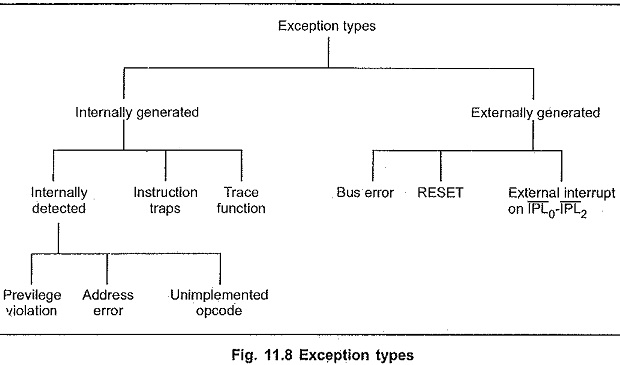
1.Internally generated exceptions
Internally generated exceptions result from the execution of certain instructions, or from internally detected errors. These can be further classified as
a)Internally detected errors
b)Instruction traps
c)Trace function
a) Internally detected errors
Privilege violation : Exception processing is initiated if you attempt to execute following instructions in the user mode : STOP, RESET, RTE, MOVE to SR, AND (Word) immediate to SR, EOR (Word) immediate to SR, OR (Word) immediate to SR, MOVE USP.
Addressing errors : Whenever 68000 attempts to access word data, long word data, or an instruction at an odd address, this is an address error since all such accesses must be done at even address boundaries.
Illegal and unimplemented opcodes : If an instruction is fetched whose bit pattern is not one of the defined instruction bit patterns for the 68000, exception processing will be initiated.
b) Instruction traps :
These are caused by execution of a particular instruction in the program. TRAP, CHK, DIVS, DIVU which will cause exception processing to be initiated if certain condition such as arithmetic overflow or divide by zero is detected.
c) Trace function :
If the T-bit in the supervisor portion of the status register is set, exception processing will be initiated after each instruction. The Trace function is used to implement single stepping through programs.
2.Externally generated exception
Bus error : When BERR is pulled low by external logic (while HALT is high) exception processing is initiated.
RESET : When RESET is asserted by external logic, exception processing is initiated.
Interrupt request : This is initiated by external logic via the three interrupt request line IPL0-IPL2.
Exception Priorities:
The different types of exceptions have different priorities. The following table lists the types of exception according to their relative priorities, and also defines when processing begins for different types of exception.
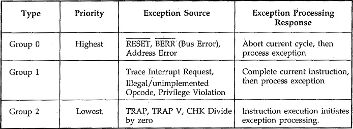
RESET, BERR, and Address Error are the highest priority exceptions. Any of these exceptions will cause immediate termination of the current instruction, even within a bus cycle. The next group of exceptions is trace, interrupt requests, illegal/unimplemented instructions, and privilege violations. These exceptions allow the completion of current instruction before initializing exception processing. The lowest priority of exceptions are TRAP, TRAPV, CHIC, and Divide by zero. These instructions can initiate exception processing as part of their normal execution.
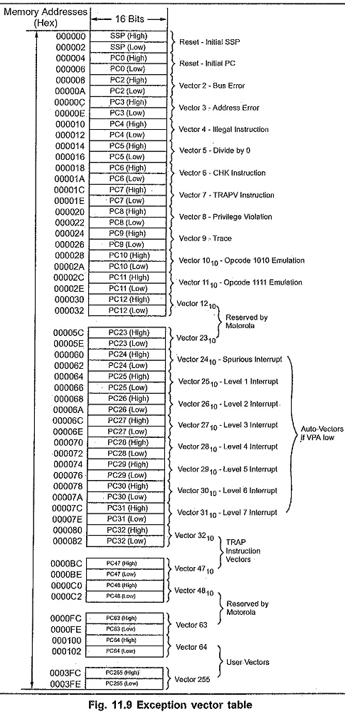
Fig. 11.9 shows Exception Vector Table. The table is organized as 256 double word (32-bit) vectors. Each vector is a 32-bit address which will be loaded into the program counter as part of the exception processing sequence.
Exception Processing Sequence:
We have seen different Exceptions Types of Motorola 68000. While processing these exceptions the 68000 follows certain sequence of operations. These operations slightly vary for different types of exception. Now we will see how 68000 responds to the different types of exceptions.
A) Exception Processing Sequence for TRAP instruction, an illegal or unimplemented opcode, or a privilege violation:
Steps :
- The Status Register contents are copied into an internal register.
- The S-bit, in the Status Register is set, thus placing the MC68000 in the Supervisor mode of operation.
- 3.The T-bit in the Status Register is reset to disable trace operation.
- The Program Counter contents are pushed onto the Supervisor stack. The contents of SSP will be decremented by four since four bytes are required to store the 32-bit contents of PC.
- Status register contents. are pushed onto the Supervisor stack; SSP contents are decremented by two, since the Status register is a 16-bit register.
- The new Program Counter contents are taken from the appropriate location in the interrupt vector table.
- Instruction execution then begins at the location indicated by the new contents of the Program Counter; this will be the first instruction of the exception processing program you have provided for that particular type of exception.
B) Exception Processing Sequence for Bus Error and Address Error:
Steps :
- The contents of the Status register are copied into an internal register.
- The S-bit in the Status register is set, placing the MC68000 in the Supervisor
- The T-bit in the Status register is reset to disable trace operation.
- The contents of the Program Counter are pushed onto the Supervisor stack and the System Stack Pointer (SSP) is decremented by four.
- The contents of the Status register are pushed onto the Supervisor stack and the contents of SSP are decremented by two.
- The contents of the MC68000’s instruction register, which constitute the first word of the instruction that was in progress when the bus error occurred, are pushed onto the Supervisor stack and SSP is decremented by two.
- The 32-bit address that was being used for the bus cycle which was terminated is also pushed onto the Supervisor stack and SSP is decremented by four.
- A word which provides information as to the type of cycle that was in progress at the time of the error is pushed onto the Supervisor stack and SSP is decremented by two.
- The Program Counter contents are taken from the appropriate interrupt vector-either the bus error vector or address error vector of the exception vector table.
- Instruction execution resumes at the location indicated by the new contents of the Program Counter.
C) Exception Processing Sequence for RESET:
Steps :
- The S-bit in the Status register is set; placing the MC68000 in the Supervisor
- The T-bit in the Status register is reset to disable the trace function.
- All three interrupt mask bits in the Status register are set, thus specifying the interrupt priority mask at level seven,
- Supervisor Stack Pointer (SSP) is loaded with the contents of the first four bytes of memory (addresses 000000-000003).
- The Program Counter (PC) is loaded from the next four bytes of memory (addresses 000004-000007).
- Instruction execution commences at the address indicated by the new contents of the Program Counter, which should reference your power-on reset initialization program.
D) Exception Processing for Interrupt Request:
An external device requests an interrupt by encoding an interrupt request level on the IPL0-IPL2 inputs. The 68000 compares these inputs to the interrupt mask bits in the status register. If the encoded priority level is higher than the level established by the interrupt mask, interrupt request will be processed.
Steps:
- The contents of the status register are saved internally.
- The S-bit in the status register is set, placing the MC68000 in the supervisor
- The T-bit in the, status register is reset to disable the trace function.
- The interrupt mask bits in the Status register are updated to the level of the interrupt request that is encoded on the IPL0-IPL2 This allows the current interrupt to be processed without being interrupted by lower priority events.
- Then 68000 performs interrupt acknowledge (INTA) bus cycle. This cycle serves two functions. The processor informs the requesting device that its interrupt request is The processor fetches an exception vector byte from the requesting device.
11.10 shows the interrupt acknowledge cycle:
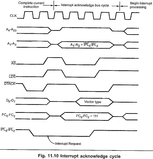
The requesting device places a byte of exception vector data on the lower byte of the data bus (D0-D7). The Data Transfer Acknowledge (DTACK) signal is used to effect this transfer of data just as with a normal read cycle. Throughout the interrupt acknowledge cycle, the Function Code Outputs (FC0-FC2) will be set high since these represent the interrupt acknowledge function code.
Address lines A1-A3 reflect the status of IPL0-IPL2.
- The contents of the program counter are pushed onto the supervisor stack and SSP is decremented by four.
- The contents of the status register are pushed onto the supervisor stack and SSP is decremented by two.
- The program counter is loaded with four bytes from the appropriate location in the exception vector table.
- Instruction execution resumes at the location indicated by the new contents of the program counter.
Spurious Interrupt:
interrupt acknowledge cycle, if requesting device responds by asserting BERR instead of DTACK, the Exceptions Types of Motorola 68000 treats this interrupt request as Spurious Interrupt Request. For spurious interrupt, the 68000 uses vector 24 in the exception vector table to load the program counter.
Autovector Interrupt Response:
Seven vector locations are used in the exception vector table for autovectors, corresponding to seven interrupt priority levels. These vectors will be used if the device requesting an interrupt responds to the interrupt acknowledge bus cycle by asserting the Valid Peripheral Address (VPA), signal instead of supplying a byte of vector data.