Motorola 68000 Pins and Signals:
Fig. 11.3 illustrates the Motorola 68000 Pins and Signals.
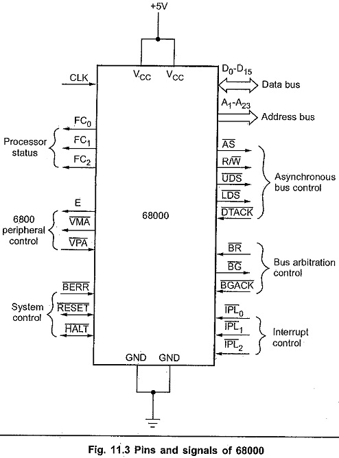
Data Transfer Control and Address Lines:
D0-D15 is the bi-directional 16-bit data bus. A1-A23 is the output 24-bit address bus. The UDS (Upper Data Strobe) and LDS (Lower Data Strobe) signals determine whether data is being transferred on either the upper (most ‘significant) byte, the lower (least significant) byte, or both bytes of the 16-bit data bus. Table defines the significance of the UDS, LDS and Read/Write (R/W) signals in relation to the data bus.
DTACK : This is an input signal to 68000 from an external device to notify that the data transfer operation is completed (either read or write).
R/W : Determines whether a read or rite operation is being performed.
1 = read, 0 = write.
Function Code Signals:
FC0,FC1 and FC2 are the function code or processor cycle status outputs. These outputs identify the type of the bus activity currently being performed by the Motorola 68000 Pins and Signals. As summarized in. Table 11.2, five different types of cycles are currently defined : access to either supervisor data memory, supervisor program memory, user data memory or user program memory, and interrupt acknowledge cycle.
System Control Signals:
BERR (BUS error) : The purpose of the BERR signal is to inform the 68000 when an external device has not responded (using the DTACK input) within an expected amount of time during a read or write operation. When this signal is active (low) the 68000 performs a sequence (exception processing sequence), similar to that which it executes in response to an interrupt request.
HALT : The HALT signal performs several functions.
- It can be used in conjunction with the BERR signal to initiate rerunning of bus
- The HALT signal is also used in conjunction with the RESET signal to initialize
The low on this signal forces 68000 to go into HALT state. In this state, at the end of the cycle the Address Bus, Data Bus, and FC0-FC2 signals are all placed in the high impedance state. When 68000 is in the halted state, it does nothing – it merely waits for the HALT signal to return high.
RESET : It is a bi-directional signal that allows processor or an external device, to reset the system.. Processor can generate RESET signal by RESET instruction which asserts RESET signal for 124 clock cycles. This gives sufficient time to all the external devices to reset.
68000 Family Signals:
E, VPA, VMA : These are provided so that 6800 family devices can be easily interfaced to the Motorola 68000 Pins and Signals (Ref. Fig. 11.4). The 6800 based systems use a synchronous method of data transfer.
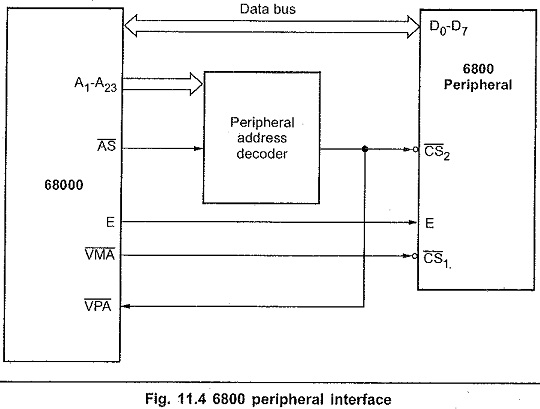
E (Clock Signal) : To accomplish synchronous data transfer, a system clock enable (E) must be distributed to all 6800 devices. The frequency of E is 1/10th of the clock input of 68000. E is low for 6 clock cycles and high for 4 clock cycles.
VPA (Valid Peripheral Address) : It is used by 6800 type devices to inform 68000 that 6800 type data transfer is required. When VPA is used, 68000 alters the data transfer timing so that it is synchronous with E.
VMA (Valid Memory Address) : If AS is still active when 68000 receives VPA, the processor responds by VMA which is used by the addressed peripheral device to complete the device selection.
Interrupt Pins:
IPL0, IPL1 and IPL2 are the interrupt request inputs. These three inputs are decoded internally by the MC 68000 to determine the priority level of the interrupt request.
Bus Arbitration Signals:
The bus arbitration is a technique used by the processor to allow bus access to any requesting device when the processor is not currently using the bus itself. The MC 68000 allows requesting devices to utilize the bus between instructions and between bus cycles of a single instruction.
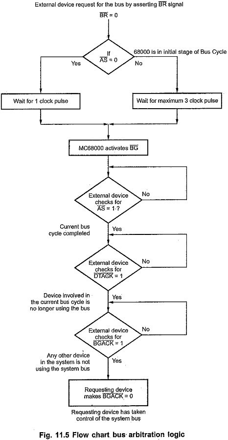
There are three signals associated with the bus arbitration logic as shown in Fig. 11.6.Bus Request (BR), Bus Grant (BG) and Bus Grant Acknowledge (BGACK). The flow chart shown in Fig. 11.5 explains how the external device takes the control of bus.
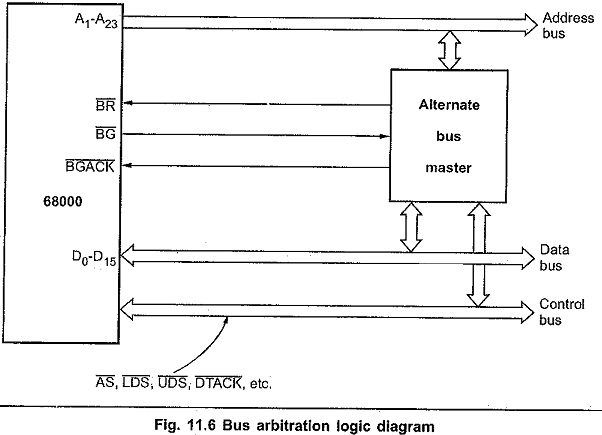
BR, BG : These signals are used, in DMA and multiprocessor applications to transfer control of the system buses from 68000 microprocessor to an external device.
BR (Bus Request) : External devices can access the system bus by asserting the BR input of Motorola 68000 Pins and Signals.
BG (Bus Grant) : On receiving BR signal 68000 relinquishes the system bus control after completing current bus cycle. It also indicates the acceptance of the request by asserting bus grant signal BG.
BGACK (Bus Grant Acknowledge) : The requesting device asserts the BGACK signal after taking the control of the system bus.