Control Signals of 8085:
The 8085 Microprocessor provides RD and WR signals to initiate read or write cycle. Because these Control Signals of 8085 are used both for reading/writing memory and for reading/writing an input device, it is necessary to generate separate read and write signals for memory and I/O devices.
The 8085 provides IO/M signal to indicate whether the initiated cycle is for I/O device or for memory device. Using IO/M signal along with RD and WR, it is possible to generate separate four Control Signals of 8085 :
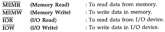
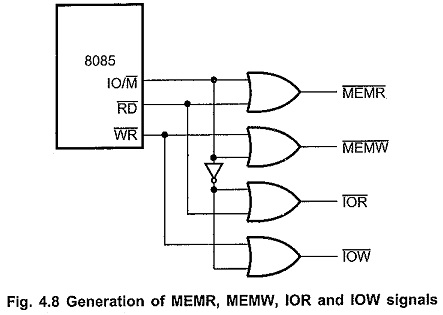
Fig. 4.8 shows the circuit which generates MEMR, MEMW, IOR and IOW signals.
We know that for OR gate, when both the inputs are low then only output is low.
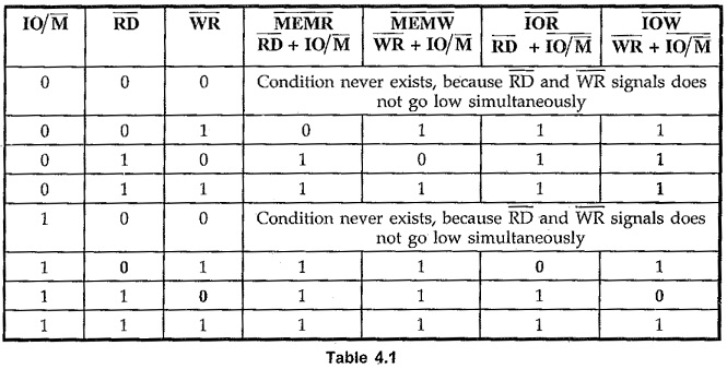
Table 4.1 shows the truth table used to generate MEMR, MEMW, IOR and IOW signals. The signal IO/M goes low for memory operation. This signal is logically ORed with RD and WR to get MEMR and MEMW signals. When both RD and IO/M signals go low, MEMR signal goes low.
Similarly, when both WR and IO/M Signals go low, MEMW signal goes low. To generate IOR and IOW signals for I/O operation, IO/M signal is first inverted and then logically ORed with RD and WR signals.
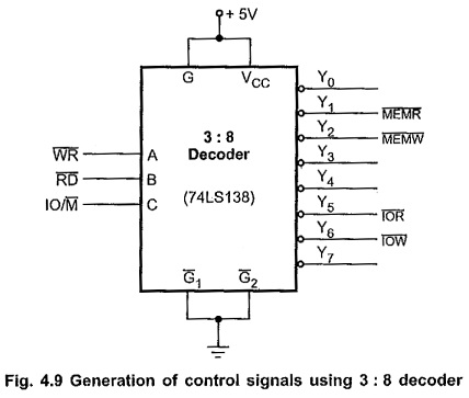
Same truth table can be implemented using 3:8 decoder as shown in Fig. 4.9.