8085 Clock Circuit:
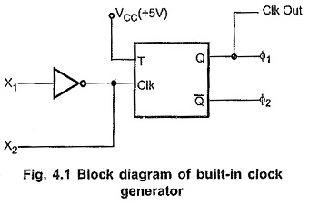
The 8085 has on chip clock generator. Fig. 4.1 shows the internal block diagram of the on chip clock generator. The internal clock generator requires tuned circuit like LC, RC or crystal, or external clock source as an input to generate the 8085 Clock Circuit. The internal T-flip flop divides the frequency by 2. Hence the operating frequency of the 8085 Clock Circuit is always half of the oscillator frequency.
LC Tuned Circuit or LC Tank Frequency:
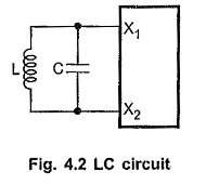
It is a LC resonant tank circuit. The resonant frequency for this circuit is given by
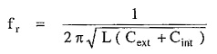
where Cint is the internal capacitance and it is normally 15 pF. The output frequency of this circuit has 10% variations. To minimize the variations in the output frequency, it is recommended to have Cext at least twice that of Cint i.e. 30 pF.
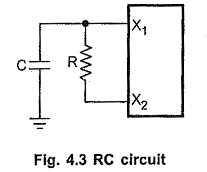
RC Tuned Circuit:
Fig. 4.3 shows the RC tuned circuit. The output frequency of this circuit is also not exactly stable. But this circuit .has an advantage that its component cost is less.
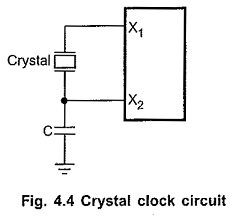
Crystal Oscillator Circuit:
Fig. 4.4 shows the crystal oscillator circuit. It is the most stable circuit. The 20 pF capacitor in the circuit is connected to assure oscillator start-up at the correct frequency.
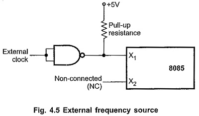
External Clock:
Fig. 4.5 shows how to drive clock input of 8085 Clock Circuit with external frequency source. Here external clock is applied at X1 input and X2 input is kept open.