Types of Interrupts in 8085:
The 8085 has multilevel interrupt system. It supports two Types of Interrupts in 8085:
- Hardware
- Software
Hardware :
Some pins on the 8085 allow, peripheral device to interrupt the main program for I/O operations. When an interrupt occurs, the 8085 completes the instruction it is currently executing and transfers the program control to a subroutine’ that services the peripheral device. Upon completion of the service routine, the CPU returns to the main program. These Types of Interrupts in 8085, where CPU pins are used to receive interrupt requests, are called hardware interrupts.
Software :
In software interrupts, the cause of the interrupt is an execution of the instruction. These are special instructions supported by the microprocessor. After execution of these instructions microprocessor completes the execution of the instruction it is currently executing and transfers the program control to the subroutine program. Upon completion of the execution of the subroutine program, program control returns to the main program.
1. Interrupt Structure of 8085:
Hardware Interrupts In 8085
The Interrupt Structure of 8085 has five hardware, namely :
(a) TRAP (b) RST 7.5 (c) RST 6.5 (d) RST 5.5 (e) INTR
When any of these ping, except INTR, is active, the internal control circuit of the 8085 produces a CALL to a predetermined memory location. This memory location, where the subroutine starts is referred to as vector location and such interrupts are called vectored interrupts. The INTR is not a vectored interrupt. It receives the address of the subroutine from the external device.
In Types of Interrupts in 8085 except TRAP are maskable. When logic signal is applied to a maskable interrupt input, the 8085 is interrupted only if that particular input is enabled. These interrupts can be enabled or disabled under program control. If disabled, 8085 disables an interrupt request. The interrupt TRAP is nonmaskable whish means that it is not maskable by program control. The Fig. 5.2 shows the interrupt structure of 8085. The figure indicates that, the 8085 is designed to respond to edge triggering, level triggering or both.
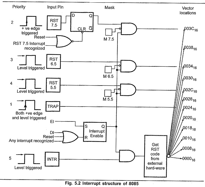
TRAP : This Types of Interrupts in 8085 is a nonmaskable interrupt. It is unaffected by any mask or interrupt enable. TRAP has the highest priority. TRAP interrupt is edge and level triggered. This means that the TRAP must go high and remain high until it is acknowledged. This avoids false triggering caused by noise and transients.
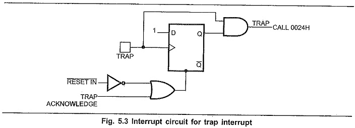
As shown in the Fig. 5.3, the positive edge of TRAP signal sets the D flip-flop. However, due to the AND gate, it is necessary to sustain high level on the TRAP input.
There are two ways to clear TRAP interrupt :
- By resetting microprocessor i.e. giving a low signal on RESETIN pin (External signal).
- By giving a high TRAP ACKNOWLEDGE (Internal signal).
After recognition of TRAP interrupt; 8085 internally generates a high TRAP ACKNOWLEDGE which clears the flip flop. Once the TRAP is acknowledged, the 8085 completes its current instruction. It then pushes the address of the next instruction i.e. return address onto the stack and loads PC with the fixed vector address 0024H. Due to this, 8085 starts execution of instructions from address 0024H which is the starting address of an interrupt service routine for TRAP.
RST 7.5 : The RST 7.5 interrupt is a maskable interrupt. It has the second highest priority. As shown in Fig. 5.2, it is positive edge triggered and the positive edge trigger is stored internally by the D-flip flop until it is cleared by software reset using SIM instruction or by internally generated ACKNOWLEDGE signal.
The positive edge signal on the RST 7.5 pin sets the D flip flop. If the mask bit M 7.5 is 0 i.e. RST 7.5 is unmasked then 8085 completes its, current instruction. It then pushes the address of the next instruction onto the stack and loads PC with the fixed vector address 003CH. Due to this, 8085 starts execution of instructions from address 003CH which is the starting address of an interrupt service routine for RST 7.5.
RST 6.5 and RST 5.5 : The RST 6.5 and RST 5.5 both are level triggered. These Types of Interrupts in 8085 can be masked using SIM instruction. The RST 6.5 has the third priority whereas RST 5.5 has the fourth priority. The vector addresses of RST 6.5 and RST 5.5 are 0034H and 002CH respectively. After recognition of RST 6.5 or RST 5.5 interrupt, 8085 completes its current instruction; pushes the address of next instruction onto the stack and loads PC with corresponding vector address.
INTR: INTR is a maskable interrupt, but not the vector interrupt. It has the lowest priority. The following sequence of events occur when INTR signal goes high.
- The 8085 checks the status of INTR signal during execution of each instruction.
- If INTR signal is high, then 8085 completes its current instruction and sends an active low interrupt acknowledge signal (INTA) if the interrupt is enabled.
- In response to the INTA signal, external logic places an instruction OPCODE on the data bus. In the case of multibyte instruction, additional interrupt acknowledge machine cycles are generated by the 8085 to transfer the additional bytes into the microprocessor.
- On receiving the instruction, the 8085 saves the address of next instruction on stack and executes received instruction.
Note : Theoretically, the external logic can place any instruction code on the data bus in response to the INTA. However, only CALL and RST codes save the contents of the PC on the stack and branch program control to the subroutine address.
Response for RST instruction : If the external device places an opcode for any one of the RST instruction (RST 0 – RST 7), then 8085 pushes the contents of PC onto the stack. It then branches the program control to the vector address of the corresponding RST instruction.
Response for CALL instruction : If the external device places an opcode for CALL instruction then 8085 generates two additional interrupt acknowledge cycles.
- It sends an active low interrupt acknowledge signal second time.
- In response to second INTA signal, external logic places the lower byte address for the CALL instruction.
- After receiving lower byte address, 8085 sends the third interrupt acknowledge
- In response to third INTA signal, external logic places the higher byte address for the CALL instruction.
- After receiving sixteen bit address for CALL, 8085 pushes the contents of the PC onto the stack and branches the program control to the subroutine whose address is received from the external logic.
Example : The Fig. 5.4 shows the diagram of external logic that gives the RST 7 instruction opcode on interrupt acknowledge.
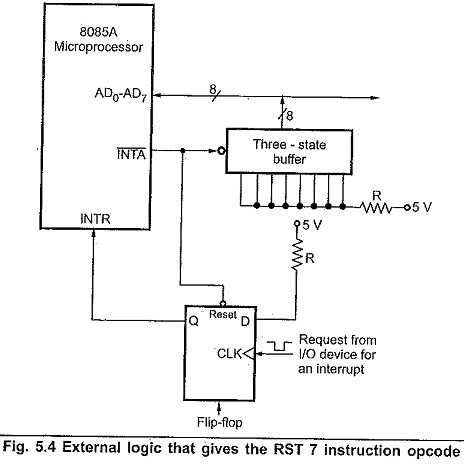
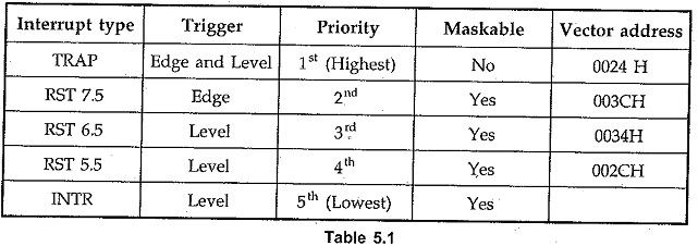
External logic controls a tri-state buffer with the INTA signal in order to place an opcode for RST 7 instruction. The INTA signal from the microprocessor is used as an Output Enable signal for the buffer as well as reset signal for D flip flop. The request from the I/O device is routed through the D flip-flop to the INTR. The D flip flop is used to hold the INTR signal high until Types of Interrupts in 8085 acknowledge signal. The INTA signal that is generated enables the tri-state buffer whose data inputs are hardwired to the value equal to the opcode for RST 7 (FFH) instruction, The 8085 receives this opcode during interrupt acknowledge cycle. After receiving the opcode 8085 pushes the contents of program counter onto the stack, thus saving the return address. It then branches the program control to the address 0038H (Vector address of RST 7). Table 5.1 shows the summary of hardware interrupts in 8085.
2. Software Interrupts in 8085:
The 8085 has eight software interrupts from RST 0 to RST 7. The vector address for these interrupts can be calculated as follows.
Interrupt number x 8 = vector address
3. Maskable and Non Maskable Interrupts in 8085:
As mentioned earlier, maskable interrupts are enabled and disabled under program control. In this section we will see how interrupts can be masked or unmasked using program control. There are four instructions used for control of interrupts :
- EI
- DI
- RIM
- SIM
EI : Enable Interrupt
The EI instruction sets the interrupt enable flip flop, as shown in Fig. 5.2. Thus RST 7.5, RST 6.5, RST 5.5 and INTR are enabled using EI instruction.
It is important to note that when any interrupt is acknowledged, interrupt enable flip flop resets and disables all interrupts. To enable interrupt in further process it is necessary to execute EI instruction within interrupt service routine.
DI : Disable Interrupt
The DI instruction resets the interrupt enable flip flop, as shown in Fig. 5.2. Thus it disables RST 7.5, RST 6.5, RST 5.5 and INTR interrupts.
SIM : Set Interrupt Mask
This instruction is used to set interrupt mask and to send serial output. It transfers the contents of accumulator to interrupt control logic and serial I/O port. Thus it is necessary to load appropriate contents in the accumulator before execution of SIM instruction.
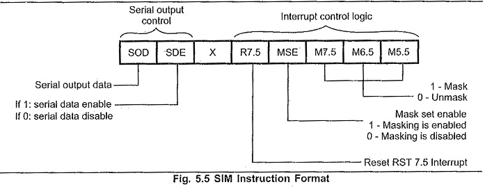
4. SIM Instruction Format :
Bits 0 – 2 will set/reset the mask bits for RST 5.5, RST 6.5, and RST 7:5 of the interrupt mask register.
Bit 3 enables the functioning of bits 0 – 2. It enables or disables the masking control.
Bit .4 is used to reset RST 7.5 request; regardless of whether or not RST 7.5 is masked.
Bit 5 is don’t care.
Bit 6 enables the serial output if it is set.
Bit 7 decides the data to be sent on the serial output pin of 8085.
5. Pending Interrupts:
RIM : Read Interrupt Mask
The Read Interrupt Mask, RIM, instruction loads the status of the interrupt mask, the pending interrupts and the contents of the serial input data line, SID, into the accumulator. Thus, it is possible to monitor status of interrupt mask, pending interrupts and serial input. There are number of Types of Interrupts in 8085. When one interrupt is being serviced, other interrupt requests may occur. If the interrupt requests are of higher priority, 8085 branches program control to the requested interrupt service routines. But when the interrupt requests are of lower priority, 8085 stores the information about these interrupt requests. Such interrupts are called pending interrupts. The status of pending interrupts can be monitored using RIM instruction.
RIM Instruction Format :
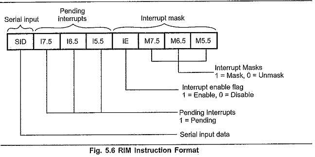
Bits 0-2 give the status of interrupt mask. Logic 1 indicates the interrupt is masked.
Bit 3 gives the status of interrupt enable flag. If 1, interrupts are enabled.
Bits 4-6 give the status of pending interrupts.
Bit 7 gives the status of serial input data line.
6. Interrupt Driven I/O:
Fig. 5.7 shows the 8 keys are connected to the microprocessor using interrupt driven I/O technique.
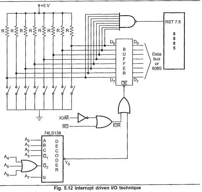
When none of the key is pressed, all input lines are high and the output of 8 input NAND gate is low. If any key is pressed, the status of that line becomes zero and the NAND gate output goes high which gives the interrupt signal to the 8085. Then microprocessor executes the interrupt service routine to check which key is pressed.
In this system, it is not necessary for microprocessor to check whether key is pressed or not in between the program execution. Here, when key is pressed interrupt is automatically generated and it initiates I/O data transfer so it is referred as interrupt driven I/O.