Interfacing 8251 with 8085:
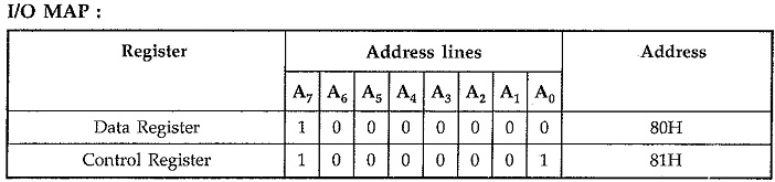
Fig. 14.44 shows the Interfacing 8251 with 8085 in I/O mapped I/O technique. Here, RD and WR signals are activated by CPU when IO/M signal is high, indicating I/O bus cycle.
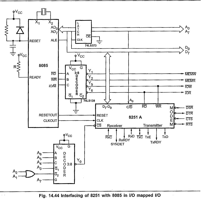
The address line A0 is connected to the C/D input .of the 8251A. The RESET and CLK signals are driven from the RESETOUT and CLKOUT signals of the 8085, respectively.
Interfacing 8251A in Memory Mapped I/O:
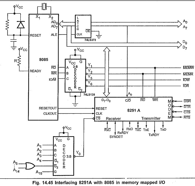
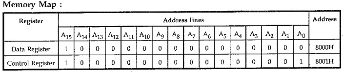
Fig. 14.45 shows the interfacing of 8251A with 8085 in memory mapped I/O technique. Here, RD and WR signals are activated when IO/M signal is low, indicating memory bus cycle. To get absolute address, all remaining address lines (A1—A15) are used to decode the address for 8251A. Other signal connections are same as in I/O mapped I/O.
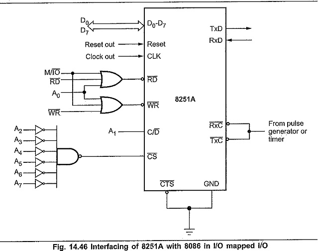
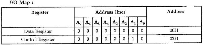
Interfacing 8251A to 8086 in I/O Mapped I/O Mode:
Fig. 14.46 shows the interfacing of 8251A with 8086 in I/O mapped I/O technique. Here, RD and WR signals are activated when M/IO signal is low, indicating I/O bus cycle. Only lower data bus (D0 – D7) is used as 8251A is 8-bit device. Reset out signal from clock generator is connected to the reset signal of the 8251A.
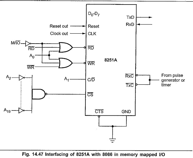
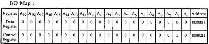
Interfacing 8251A to 8086 in Memory Mapped I/O:
In this type of I/O interfacing, the 8086 uses 20 address lines to identify an I/O device; an I/O device is connected as if it is a memory register. The 8086 uses same control signals and instructions to access I/O as those of memory. Fig. 14.47 shows the interfacing of 8251A with 8086 in memory mapped I/O technique. Here, RD and WR signals are activated when M/IO signal is high, indicating memory bus cycle. Address line A1 is used to select either data register, or control register. The remaining address lines A2-A19 are used to decoder the addresses for 8251A.
Programming Examples:
To implement serial communication the CPU must inform the 8251A all details such as mode, baud rate (in case of asynchronous mode), stop bits, parity etc. Therefore, prior to data transfer, a set of control words must be loaded into the mode instruction and control instruction registers of 8251A,