8251 Usart:
We know that, 8251A is Universal Synchronous, Asynchronous, Receiver, and Transmitter. Therefore 8251 Usart can take place with four different ways.
-
Asynchronous transmission
-
Asynchronous reception
-
Synchronous transmission
-
Synchronous reception
These communication modes can be enabled by writing proper mode and command instructions. The mode instruction defines the baud rate (in case of asynchronous mode), character length, number of stop bit(s) and parity type. After writing proper mode instruction it is necessary to write appropriate command instruction depending on the communication type.
1.Asynchronous Transmission:
Transmission can be enabled by setting transmission enable bit (bit 0) in the command instruction. When transmitter is enabled and CTS = 0 the transmitter is ready to transfer data on TxD line.
Operation :
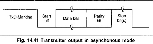
When transmitter is ready to transfer data on TxD line, CPU sends data character and it is loaded in the transmit buffer register. The 8251 Usart then automatically adds a start bit (low level) followed by the data bits (least significant bit first), and the programmed number of STOP bit(s) to each character. It also adds parity information prior to STOP bit(s), as defined by the mode instruction. The character is then transmitted as a serial data stream on the TxD output at the falling edge of TxC. The rate of transmission is equal to 1, 1/16 or 1/64 that of the TxC, as defined by the mode instruction. Fig. 14.41 shows the transmitter output in the asynchronous mode.
2.Asynchronous Reception:
Reception can be enabled by setting receive enable bit (bit 2) in the command instruction.
Operation :
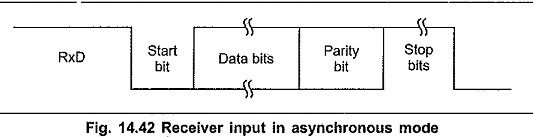
The RxD line is normally high. 8251A looks for a low level on the RxD line. When it receives the low level, it assumes that it is a START bit and enables an internal counter. At a count equivalent to one-half of a bit time, the RxD line is sampled again. If the line is still low, a valid START bit is detected and the 8251A proceeds to assemble the character. After succesful reception of a START bit the 8251A receives data, parity, and STOP bits and then transfers the data on the receiver input register. The data is then transferred into the receiver buffer register. Fig. 14.16 shows the receiver input in the asynchronous mode.
3.Synchronous Transmission:
Another 8251 Usart is Transmission can be enabled by setting transmission enable bit (bit 0) in the command instruction. When transmitter is enabled and CTS = 0, the transmitter is ready to transfer data on TxD line.
Operation :
When transmitter is ready to transfer data on TxD line, 8251A transfers characters serially out on the TxD line at the falling edge of the. TxC. The first character usually is the SYNC character.
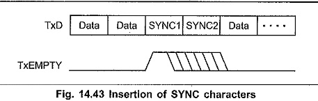
Once transmission has started, the data stream at the TxD output must continue at the TxC rate. If CPU does not provide 8251A with a data character before transmitter buffers become empty, the SYNC characters will be automatically inserted in the TxD data stream, as shown in the Fig. 14.43. In this case, the TxEMPTY pin is raised high to indicate CPU that transmitter buffers are empty. The TxEMPTY pin is internally reset when CPU writes data character in the transmitter buffer.
4.Synchronous Reception :
Reception can be enabled by setting receive enable bit (bit 2) in the command instruction.
Operation :
In this 8251 Usart, character synchronization can be achieved internally or externally.
Internal SYNC To detect the SYNC character 8251A should be programmed in the ‘Enter HUNT’ mode by setting bit 7 in the command. insturction. Once 8251A enters in the ‘Enter HUNT’ mode it starts sampling data on the RxD pin on the rising edge of the RxC. The content of the receiver buffer is compared at every bit boundary with the first SYNC character until a match, occurs. If the 8251A has been programmed for two SYNC characters, the subsequent SYNC characters are compared until the match occurs. Once 8251A detects SYNC character(s) it enters from ‘HUNT’ mode to character synchronization mode, and starts receiving the data characters on the rising edge of the next RxC. To indicate that the synchronization is achieved 8251A sets the SYNDET pin high. It is reset automatically when CPU reads the status register.
External SYNC:
In the external SYNC mode, synchronization is achieved by applying a high level on the SYNDET pin, thus forcing the 8251A out of the HUNT mode.