Power on Reset Circuit in 8051:
On reset, the PC sets to 0000H which causes the 8085 to execute the first instruction from address 0000H. For proper reset operation reset signal must be held low for at least 3 clock cycles. The power-on Reset Circuit of 8085 can be used to ensure execution of first instruction from address 0000H. Fig. 4.7 shows the power-on Reset Circuit of 8085 with typical R, C values. (Note : R, C values may vary due to power supply ramp up time).
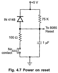
Upon power-up, RESET IN must remain low for at least 10ms after minimum Vcc has been reached, in the circuit shown in Fig. 4.7. Upon power up or key press, the RESET IN goes low and slowly rises to +5V, providing sufficient time for the processor to reset the system. The diode is connected to discharge the capacitor immediately when power supply is switched OFF.
After RESET, 8085 loads 0000H in PC register and clears the INTE flag. Before going to execute interrupt service routine, it is necessary to setup certain parameters, required to execute interrupt service routine. To avoid interrupt to occur before completion of these initial requirements, after power on or reset, INTE flip-flop is cleared to disable interrupts. It can be enabled by EI instruction after initial settings.
As we know that, after power up or Reset Circuit of 8085 fetches its first instruction from 0000H address, and it has to be the first instruction from monitor program. Therefore EPROM consisting of monitor program must be located from address 0000H in any Supporting Circuits of 8085 Microprocessor.