Distance Relays Types and their Applications:
In applying relays to a transmission system it is necessary to state the relay characteristic in the same terms that the system conditions are stated. This is especially true of Distance Relays Types. If the relay characteristics are thought of in terms of volts and amperes, then the system conditions should be stated in the same terms. With the distance relays, however, it is difficult to think in terms of volts and amperes, because these values vary widely for the same relay response. This relay response is some function of the ratio between volts and amperes and for any given value of the ratio there may exist an infinite number of values of the volts and amperes. It, therefore, simplifies matters greatly to think of the distance relay response in terms of the ratio of volts to amperes or in other words to think of impedance, reactance, resistance or combination thereof to which the relay responds. However in designing Distance Relays Types it is necessary to think in terms of the volts, amperes and phase angle to which it must respond because these are the quantities which actually operate the contact actuating parts.
Relay Types and Their Application:
Principal Distance Relays Types are:
- impedance;
- reactance;
- admittance (mho);
- ohm; and
- offset mho.
The common types compare two input quantities either in magnitude or in phase. Any of the relay characteristics can be obtained either by an amplitude comparator or by a phase comparator.
Impedance Replay:
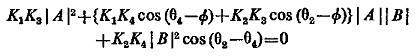
This is a device which measures distance by comparing the fault current I with the voltage V across the fault loop. It is simple in this case to have an amplitude comparator and the balanced beam type structure is most common. The equation for the amplitude comparator at threshold as derived already in Eq. (4.4) is
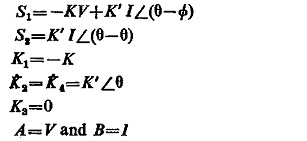
If the constants are so adjusted that the input signals are
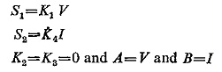
Substituting these conditions in the above equation, we get
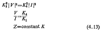
The characteristics when plotted on the R-X plane is shown in Fig. (4.16) which is a circle with origin as its centre; signifying that a simple
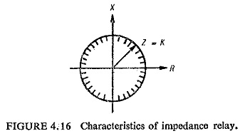
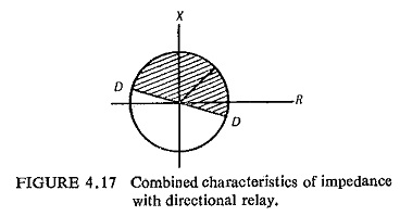
impedance relay would operate for any value of impedance lying within the circle. The characteristic also depicts that the relay is not directional and it is essential to provide a directional relay along with an impedance relay. The combined characteristics of an impedance and directional relay are shown in Fig. (4.17) where DD represents the directional relay characteristic and the operating region is the shaded portion.
Reactance Replay:
All other relays except the impedance relay are conveniently obtained by A phase comparator. The basic equation for a phase comparator already derived in Eq. (4.6) at threshold is
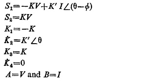
Using the input signals in the following manner
Substituting these conditions in the above equation, we have
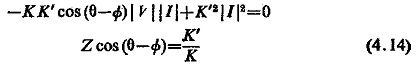
Now if θ is π/2 the above equation reduces to the reactance form, i.e.
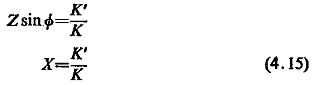
When plotted on the R-X diagram the characteristic is represented by a straight line parallel to the horizontal axis it as in Fig. (4.18).
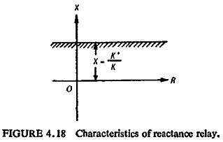
With some predetermined setting of value of X, the relay will measure any value of reactance below the setting. A reactance relay responds only to the reactive component of system impedance; consequently it is unaffected by fault arc resistance. However, when fault resistance is such a high value that load and fault current magnitudes are comparable the reach of the relay is modified by the value of the load and its power factor and may either overreach or underreach.
Voltage-restrained starting relays are used in a reactance measuring scheme to give directional response and to prevent operation on load. The reactance relay as seen by Eq. (4.15) is a particular case of an ohm relay, in which the angle of compensation θ is 90°.
Admittance (MHO) Relay:
If the signals S1 and S2 given to the phase comparator are
Substituting these conditions in Eq. (4.6) we have
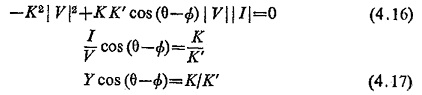
This represents the admittance or the mho characteristic and when plotted on the R-X diagram is a circle passing through the origin and when plotted on the G-B diagram is a straight line as illustrated in Fig. (4.19).
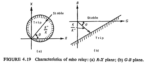
The circle passing through the origin makes it inherently directional. With such a characteristic the relay measures distances in one direction only.
From the expression (4.16) it is evident that the relay is inoperative if the voltage falls to zero, because both terms contain V. A memory circuit may be used to prevent the immediate decay of voltage applied to the relay terminals when a closeup three-phase short circuit occurs. This enables high speed mho protection to operate correctly on closeup faults, provided that the protected circuit is energised before the short circuit is applied.
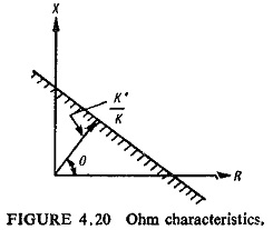
OHM Relay:
As explained earlier a reactance relay is a particular case of an ohm relay. Its characteristic is represented by Eq. (4.14) when plotted on the R-X plane is a straight line (Fig. (4.20)). The ohm relay is used as a supplementary element to modify the operating region of the other types of measuring elements.
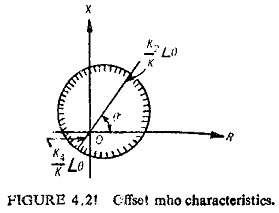
OFFSET MHO Relay:
Let the signals S1 and S2 given to the phase comparator be
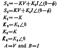
Substituting these conditions we have
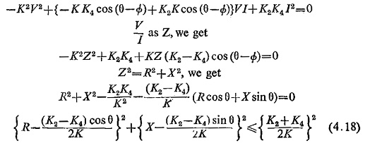
This equation represents a circle, with centre at (K2—K4)/2K∠θ on the R-X plane, the radius being of magnitude (K2 + K4)/2K. The offset threshold characteristic is shown in Fig. (4.21).