Time Grading of Distance Relay:
Two methods of Time Grading of Distance Relay are shown in Fig. (5.18). First Method is the distance time method at (a) has the operating time increasing steadily with increasing distance between the relay location and the fault. For coordination of relays on consecutive sections as shown in Fig. (5.18a) tA – tB should be equal to 0.5s so that for faults on section BC the relay at B operates first and the relay at A acts as a backup protection. Similarly tB – tC should be 0.5s. Obviously this type of protection is a slow-speed protection and is unsuitable for transmission systems where fast fault clearance is essential to maintain stability.
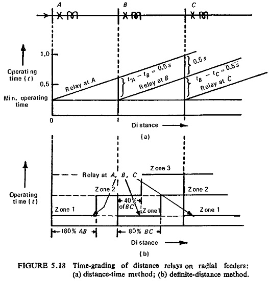
Second Method of Time Grading of Distance Relay is the definite distance method at (b) has stepped characteristics in three stages. Zone 1 of the relay provides instantaneous tripping for any fault within a predetermined distance from the relay (generally 80% of the protected feeder). Zone 2 operates with a time delay and covers the remainder of the protected feeder and backs up the protection on the next feeder for about 40% of that feeder. After a further time delay the range of the distance relays is further extended to zone 3, which is used as backup protection only.
The time delay between the various zones is chosen according to stepped principle (usual value of time delay step is 0.5s). Obviously this is a high speed protection and has superseded the distance-time protection. Besides, the construction of definite-distance relays is simpler than distance-time relays. Because of this only high-speed distance relays are widely used in practice. Such relays can be arranged for measuring impedance or reactance and are normally provided with built-in directional feature.
Hence the basic features involved in such a relay are (i) impedance or reactance measurement, (ii) direction and (iii) timing.
For finding the pickup value of the impedance in section n let us say zone 1 is 80% of the protected section.
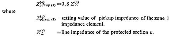
Therefore, any phase-fault for which the impedance seen by the relay is less than the setting value of pickup impedance for zone 1 will belong to zone 1 and is cleared instantaneously.
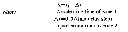
The zone 2 includes the whole length of protected section plus 40% of the next adjacent section. The clearing time for the zone 2 is taken as
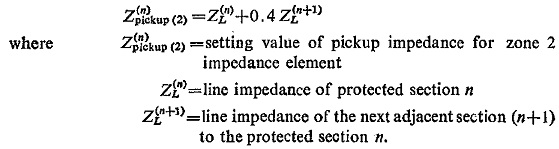
The pickup impedance for zone 2 is
It is not possible to protect the whole length of the protected section by zone 1, because of the indeterminate nature of the fault resistance which may disturb the selective operation for faults at the end of the protected section and at the beginning of the next section. This is why zone 1 is kept nearly 80% of the protected section and zone 2 protects only a little portion nearly 20% of the protected section, but this provision helps in selective operation.
Requirements of Definite-Distance Schemes:
Two feeders BO and OA are represented on the complex plane in Fig. (5. 19) considered from the point of view of relays at O. The length OA is thus proportional to the impedance of feeder OA and θ is the impedance angle of the feeder.
Zone 1 of the protection at O is required to reach up to say P. The relays at O therefore must operate for all faults between O and P only.
The effect of fault arc resistance is also shown in Fig. (5.19).
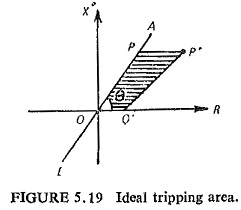
The fault resistance increases slightly for faults towards the remote end of the feeder because less of the total fault current flows through the relay. The shaded area OPP′O′ is known as fault area. The impedance seen for differing fault positions will lie inside the shaded area. To protect against all faults the relay must operate if the measured impedance lies within the fault area. Hence relays at O with characteristics which completely enclose the fault area are suitable for protection of feeder OA.