Distance Protection:
Both time-graded and pilot-wire system are not suitable for the protection of very long high voltage transmission lines. The former gives an unduly long time delay in fault clearance at the generating station end when there are more than four or five sections and the pilot-wire system becomes too expensive owing to the greater length of pilot wires required. This has led to the development of Distance Protection in which the action of relay depends upon the distance (or impedance) between the point where the relay is installed and the point of fault. This system provides discrimination protection without employing pilot wires.
The principle and operation of Distance Protection relays have already been discussed here. We shall now consider its application for the protection of transmission lines. Fig. 23.12 (i) shows a simple system consisting of lines in series such that power can flow only from left to right.
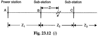
The relays at A, B and C are set to operate for impedance less than Z1 , Z2 and Z3 respectively. Suppose a fault occurs between sub-stations B and C, the fault impedance at power station and sub-station A and B will be Z1 + Z and Z respectively. It is clear that for the portion shown, only relay at B will operate. Similarly, if a fault occurs within section AB, then only relay at A will operate. In this manner, instantaneous protection can be obtained for all conditions of operation.
In actual practice, it is not possible to obtain instantaneous protection for complete length of the line due to inaccuracies in the relay elements and instrument transformers. Thus the relay at A [See Fig. 23.12 (i)] would not be very reliable in distinguishing between a fault at 99% of the distance AB and the one at 101% of distance AB. This difficulty is overcome by using ‘three-zone‘ Distance Protection shown in Fig. 23.12 (ii).
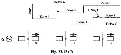
In this scheme of Distance Protection, three distance elements are used at each terminal. The zone 1 element covers first 90% of the line and is arranged to trip instantaneously for faults in this portion. The zone 2 element trips for faults in the remaining 10% of the line and for faults in the next line section, but a time delay is introduced to prevent the line from being tripped if the fault is in the next section. The zone 3 element provides back-up protection in the event a fault in the next section is not cleared by its breaker.