Principle of Distance Relaying:
The Principle of Distance Relaying is governed by the ratio of voltage to current at the relay location and the operating time of the relay automatically increases with an increase of this ratio. Now the impedance or the reactance of the circuit between the relay and the fault is proportional to the distance between them provided the relay actuating quantities (voltage and current) are properly chosen. This is the reason why such a relay is known as a distance relay.
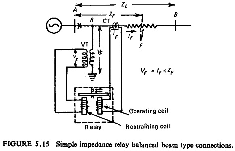
A simple example of measuring impedance of the line up to the point of fault is shown in Fig. (5.15). The relay is connected at point R and the two coils of the relay operating and restraining coils receive current (iF) and voltage (vF) proportional to the fault current IF and the faulted loop voltage VF. Below a particular value of Z=V/I the relay operates, whereas above this value of Z the relay restrains; it is possible to select a setting comparable to the length of the line to be protected.
Strictly speaking the impedance seen by the relay is not proportional to the distance between the relay and the fault in general, because of the following reasons:
- Presence of resistance at the fault location.
- Presence of loads and/or generating sources between the relay and the fault location, etc. Many a time for selective operation the relay requires the measurement of not only the magnitude but also the angle of the impedance of the line up to the fault point. However, the term Principle of Distance Relaying is used to designate the whole group consisting of impedance, reactance, mho, modified impedance, ohm, offset mho, elliptical characteristic and trapezoidal characteristic relays.
Effect of the Ratio Source Impedance to Line Impedance (ZS/ZL)
Any system could be represented by a single line diagram shown in Fig. (5.16) representing the source and the line to be protected, R being the relay location.
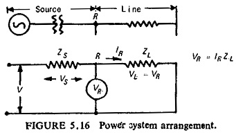
This simple impedance loop has a voltage V applied to it which actually depends on the type of fault whether phase fault or ground fault. ZS and ZL are the source impedance and the line impedance respectively. ZS is a measure of fault MVA at the relaying point, and for faults involving earth, is also dependent on the method of system earthing behind the relaying point. ZL is a measure of the impedance of the protected section. IR and VR are the current and voltage applied to the relay respectively. The voltage VR applied to the relay is thus IRZL for a fault at the reach point, and this may be alternatively expressed in terms of ZS/ZL ratio:
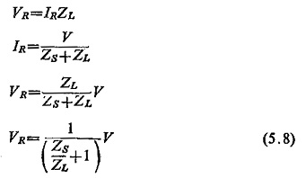
Equation (5.8) is true for all types of faults with the following rule being observed:
(1) With phase-faults V is the delta voltage and ZS/ZL is the positive sequence source impedance/positive sequence line impedance, i.e.
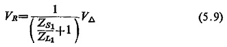
(2) With earth-faults V is the star voltage and ZS/ZL is a composite ratio involving positive and zero sequence impedance, i.e.
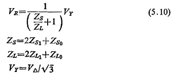
Figure (5.17) illustrates the effect of ZS/ZL ratio on the voltage at relay position R. Three fault locations are shown: fault outside the zone of protection, fault at setting distance, and fault in the protected zone.
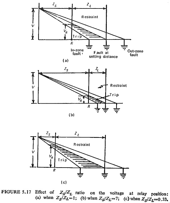
The ordinate at R represents the voltage applied to the relay VR for various fault locations, for the relay to restrain VR should be greater than the preset value of VR = IRZL and for operation VR should be less than the preset value of VR = IRZL.