Double Differentiation – Derivation:
Two R-C coupling networks in cascade separated by an amplifier A is shown in Fig. 29.36 (a). The amplifier A is to operate as a linear amplifier and the output impedance must be small with respect to the impedance of R2 and C2 so that this combination does not load the amplifier. Let R1 be the parallel combination of R and the input impedance of the amplifier. The time constants R1C1 and R2C2 must be small in comparison to the period of the input wave to enable the circuit to perform Double Differentiation.
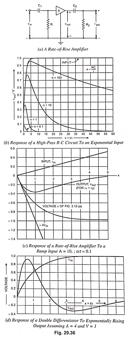
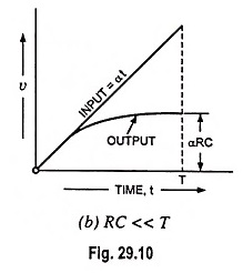
When the input is a ramp (vin = αt) of long duration, the output of the inverting amplifier is the negative of the waveform shown in Fig. 29.10 (b) and is given by equation
![]()
where A is the magnitude of the amplifier gain and τ1 is the time constant and is equal to R1C1. This exponential input to the network R2C2 in turn gives an output given by Eq. (29.16)
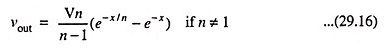
If n # 1 where n ≡ τ2/τ1, τ2 = R2C2 and x ≡ t/τ1, values of -vout/Aατ1 are plotted in Fig. 29.36 (b) for values of n equal to 0.1, 1.0, 10 and 100. For n = 1, the output is given by
![]()
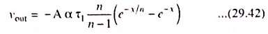
This special case is plotted in Fig. 29.36 (c).
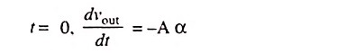
The noteworthy point is that a ramp voltage has been converted into a pulse. The initial slope of the output wave is the initial slope of the input multiplied by the amplifier gain. This is the reason that the stage in Fig. 29.36 (a) is known as “rate-of-rise-amplifier”. For a single R-C circuit, the initial rate of change of output is equal to the initial rate of change of input independently of the time constant. Obviously, the same conclusion can be arrived at for multiple differentiation. A direct check can be made from Eq. (29.42). where it is found that at
As a second illustration of Double Differentiation, we may consider the exponential waveform vin = V(1 – e-t/τ) applied to the circuit shown in Fig. 29.36 (a). For
τ1 = τ2 = τ
or R1C1 = R2C2 = τ, the output is found to be
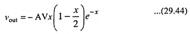
where x = t/τ. This result is plotted in Fig. 29.36 (d). The initial slope of output voltage vout is -AV/τ since V/τ is the initial slope of input voltage vin. Also, direct integration reveals that the output waveform has as much area above the time axis as below, a fact of importance in some practical problems, such as in pulse spectrometry.