Double Line to Ground Fault (LLG):
Figure 11.9 shows a Double Line to Ground Fault at F in a power system. The fault may in general have an impedance Zf as shown.
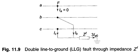
The current and voltage (to ground) conditions at the fault are expressed as
The symmetrical components of voltages are given by
from which it follows that
From Eqs. (11.22a) and (11.22b)
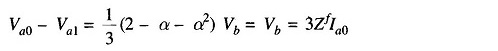
or
![]()
From Eqs. (11.19), (11.22a) and (11.23), we can draw the connection of sequence networks as shown in Figs. 11.10 a and b. The reader may verify this by writing mesh and nodal equations for these figures.
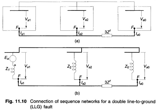
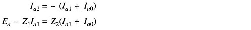
In terms of the Thevenin equivalents, we can write from Fig. 11.10b
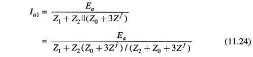
The above result can be obtained analytically as follows:
Substituting for Va1, Va2 and Va0 in terms of Ea in Eq. (11.1) and pre multiplying both sides by Z-1 (inverse of sequence impedance matrix), we get
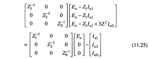
Pre multiplying both sides by row matrix [1 1 1] and using Eqs. (11.19) and (11.20), we get
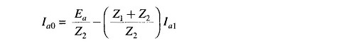
From Eq. (11.22a), we have
![]()
Substituting
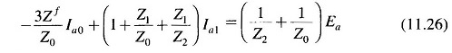
or
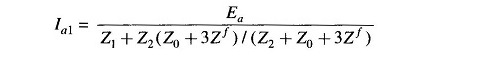
Substituting this value of Ia0 in Eq. (11.26) and simplifying, we finally get
If the Double Line to Ground Fault takes place from loaded conditions, the positive sequence network will be modified.