Second Order Low Pass Butterworth Filter Derivation:
A stop band response having a 40 db/decade roll off is obtained with a Second Order Low Pass Butterworth Filter Derivation
A second order filter can be obtained by coupling two active filters having a – 20 db/decade roll off to produce a roll off of – 40 db/decade, but this would not be economical because it requires two opamps.
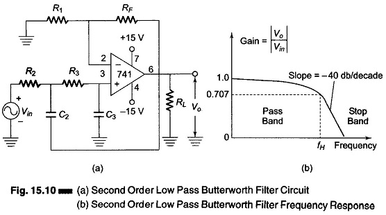
A second order filter can be obtained by the use of a single opamp first order low pass filter by simply using an additional RC network, as shown in Fig. 15.10.
The gain of the second order filter is set by R1 and RF, while the high cutoff frequency fH is determined by R2, C2, R3 and C3 as given below.

The voltage gain magnitude equation for a second order low pass Butterworth response is given by
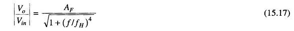
where
- AF = 1+ RF/R1 = pass band gain of the filter
- f = frequency of the input signal, in Hz
- fH = High cutoff frequencies, in Hz
The normalized Butterworth polynomials are given in Table 15.1.
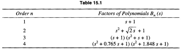
where s = jω and coefficient of s = 2 k, where k is the damping factor.
Mathematical Proof for a Second Order Low Pass Filter:
Consider a prototype second order low pass filter shown in Fig. 15.11.
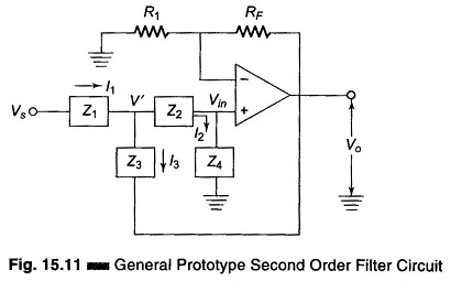
Referring to the circuit in Fig. 15.11, we see that
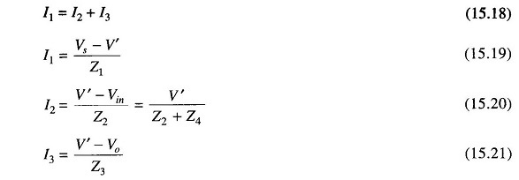
Substituting Eqs (15.19), (15.20) and (15.21) in Eq.(15.18)
we have

Also

But the open loop voltage gain Aνo = Vo/Vin, therefore
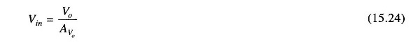
Substituting for Vin in Eq.(15.23)
Therefore
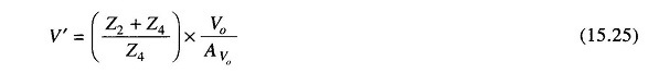
Substituting for Vin in Eq. (15.22) we have
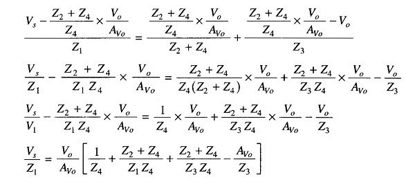
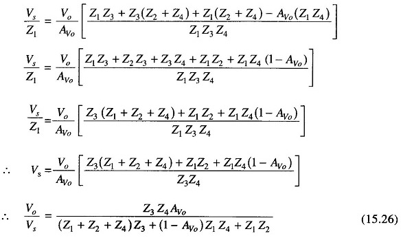
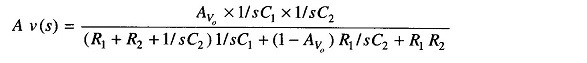
But this is equal to the transfer function(s).
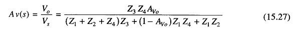
(This is the general equation.)
Therefore Z1 = R1, Z2 = R2, Z3 = 1/sC1, Z4 = 1/sC2. Now for a low pass filter, Z1 and Z2 are resistors and Z3 and Z4 are capacitors, where s is the transfer function. Therefore