Band Pass Filter:
Band pass filter pass a certain range of frequencies (called as pass band) while attenuate all other frequencies. Such band pass filters can be obtained by connecting low pass filter sections in cascade with high pass filter sections as shown in Fig. 9.15.
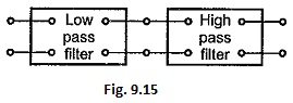
In above type of connection, the cut-off frequency of low pass filter section must be selected higher than that of high pass filter section.
Although cascade connection of low pass filter and high pass filter sections functions properly as band pass filter, it is more economical to combine both sections in one single filter section. An alternative form of band pass filter can be obtained either as a T or π section if series arm contains a series resonant circuit while the shunt arm contains a parallel resonant circuit as shown in the Fig. 9.16 (a) and (b).
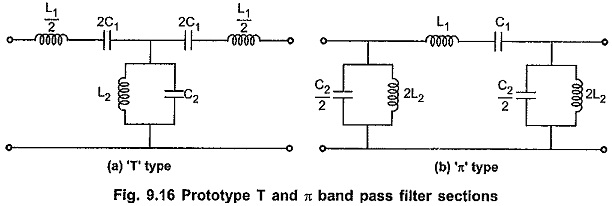
The band pass filter characteristics can be obtained by using conventional band pass filter (either T or π type) as shown in the Fig. 9.16, if the series resonant frequency of the series arm is selected same as anti resonant frequency of the shunt arm. Consider T type band pass filter section as shown in the Fig. 9.16 (a). Let the frequency of series and shunt arm be ω0 rad/sec.
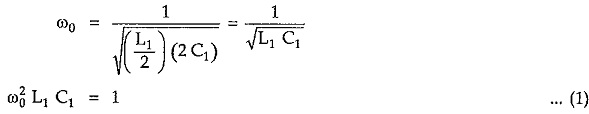
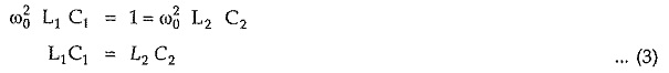
Then, for series arm, frequency of resonance is given by,
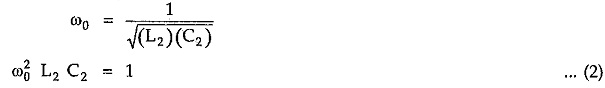
Similarly for shunt arm, frequency of anti resonance is given by,
From equations (1) and (2), for same resonant frequencies of series and shunt arms we can write,
Design Impedance (R0):
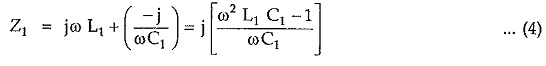
Total series arm impedance Z1 is given by
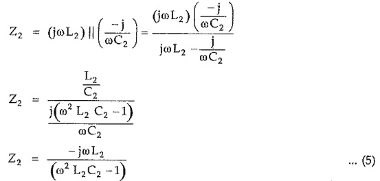
Similarly, total shunt arm impedance Z2 is given by
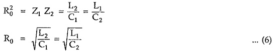
Hence, Z1 Z2 = L2/C1 = L1/C2 which is real and constant. Hence above sections are constant k sections. So we can write,
Reactance Curves and Expressions for Cut-off Frequencies:
To verify the band pass characteristics, let Z1 = j X1 and Z2 =j X2. Similar to the reactance curves drawn for low pass filter section and high pass filter section, sketching reactances X1 and (X1/4 + X2) against frequency f as shown in the Fig. 9.17.
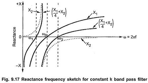
From the above characteristics it is clear that the reactance curves for X1 and (X1/4 + X2) are on the same sides the axis below f1 and above f2. At the same time, the reactance curves between f1 and f2 are on opposite sides of frequency axis. Thus frequencies between f1 and f2 constitute a pass band ; while the frequencies below f1 and above f2 give stop band. Hence the section considered shows band pass filter characteristics where f1 and f2 are lower and upper cut-off frequencies of the filter.
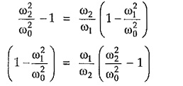
In band pass filter, condition for cut-off frequency is,
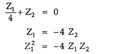
But from the condition of constant-k filter section, Z1 Z2 = R20
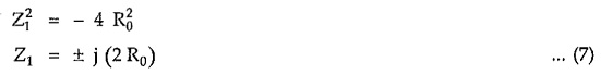
From above equation (7) it is clear that the value of the series arm impedance Z1 can be obtained at two different cut-off frequencies namely f1 and f2. So at f = f1, Z1 = – j(2 R0) and at f = f2 , Z1 = + j(2 R0). Thus impedance Z1 at f1, i.e. lower cut-off frequency, is negative of the impedance Z1 at f2 i.e. upper cut-off frequency. Hence we can write,
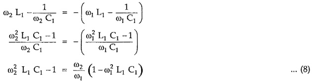
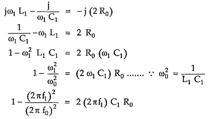
But from equation (1) we can write,
![]()
Substituting value of (L1 C1) in above equation (8), we can write,
Simplifying above equation,
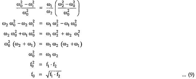
Hence, above equation (9) indicates that frequency of resonance of the individual arms is the geometric mean of two cut-off frequencies:
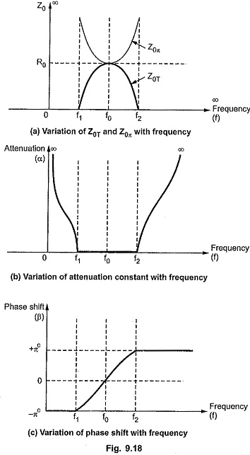
Variation of Z0T and Z0π, Attenuation Constant (α) and Phase Constant (β) with Frequency:
The variations of Z0T and Z0π, attenuation constant (α) and phase shift (β) with frequency are as shown in the Fig. 9.18. (a), (b) and (c). Consider that the design impedance of band pass filter is R0 and cut-off frequencies are f1 and f2.
Design Equations:
Consider that the filter is terminated in design impedance R0 and the cut-off frequencies are f1 and f2.
Then from equation (7), at the lower cut-off frequency f1, we can write,
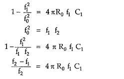
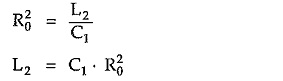
But for band pass filter constant k section
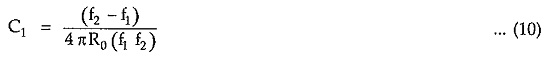
Substituting the value of C1 from equation (10),
As f20 = f1 f2, we get
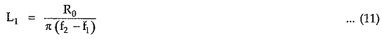
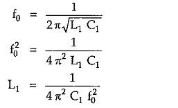
From equation (6), we can write,
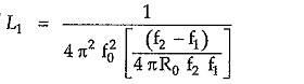
Substituting value of L1 from equation (11),
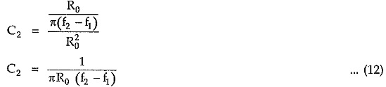
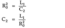
From equation.(6), we can write,
Substituting value of C1 from equation (10),
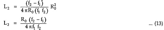
Equations (10) to (13) are called design equations of prototype band pass filter sections.