m Derived Low Pass Filter:
The m Derived Low Pass Filter T and π sections are as shown in the Fig. 9.29 (a) and (b) respectively.
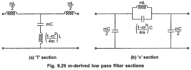
Consider that the shunt arm of T section resonates at the frequency of infinite attenuation i.e. f∞, which is selected just above cut-off frequency fc. The frequency of resonance is given by,
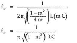
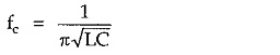
But for low pass filter, cut-off frequency is given by,
Substituting above value in equation for f∞,
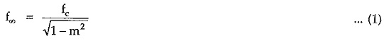
Simplifying equation (1),
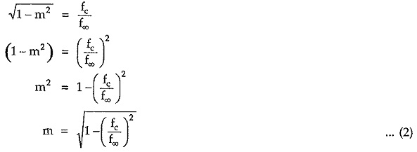
Thus, equation (2) clearly indicates that if the cut-off frequency and frequency of infinite attenuation are specified the value of m can be easily evaluated.
Variations of Characteristic Impedance (Z0) , Attenuation Constant (α) and Phase Constant (β) with Frequency:
The variations of characteristic impedance (Z0), attenuation constant (α) and phase constant (β) with frequency are as shown in the Fig. 9.30 (a), (b) and (c) respectively.
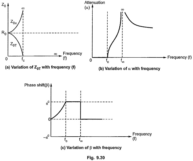
As the characteristic impedance Z0 for prototype filter and m-derived section is same, the variation of Z0 in m Derived Low Pass Filter section is similar to that in prototype filter section.
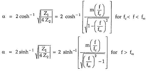
The variation of attenuation constant over the attenuation band depends on types of the reactances. The attenuation constant a in attenuation band is given by,
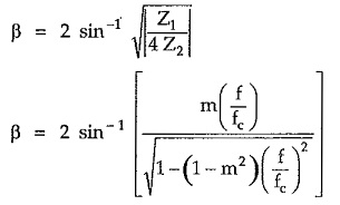
The phase shift β in pass band is given by,
As studied earlier, in stop band phase shift is always πc. But in m Derived Low Pass Filter, above f∞, the phase shift drops to 0 value as shunt arm becomes inductive above resonant frequency.