m Derived Filters:
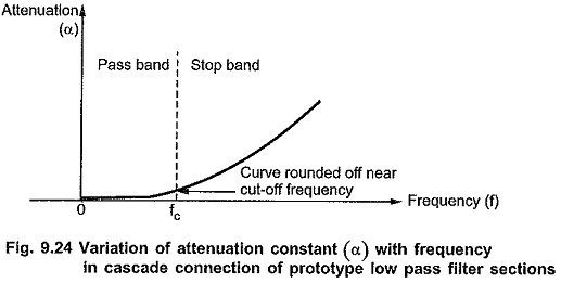
m Derived Filters – The first disadvantage of prototype filter sections can be overcome by connecting two or more prototype sections of same type (either all T type or all π type) in cascade. In such a cascade connection, attenuation to the frequencies in pass band remains zero ideally, but attenuation to the frequencies in entire attenuation band considerably increases. e.g. If two sections of same type are cascaded, the attenuation in the attenuation band gets doubled giving much sharper cut-off characteristics than that obtained by using only a single section.
But due to the resistance in the components used in cascade connection, the attenuation in pass band slightly increases, instead of being zero. Thus the curve becomes rounded off at the cut off frequency in pass band as shown in the Fig. 9.24.
To fulfill all the requirements discussed above, it is necessary to design a new section having same cut-off frequency as that of the prototype section but different attenuation characteristics in the attenuation band. Also to maintain same cut-off frequency, both the sections must have same characteristic impedance Z0. It is possible to derive a new section from a prototype constant K section. Thus, a new section derived is called m-derived section.
Derivation of m-derived Sections:
Consider any general T section and a new section derived from it as shown in the Fig. 9.25 (a) and (b).
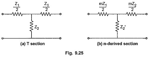
In the m-derived section, the series arm is of same type as that in prototype section but having different value i.e. m Z1/2 where m is a constant. Now Z2 of prototype section will change to Z′2 in m-derived section such that the value of Z0 for both the sections is same.
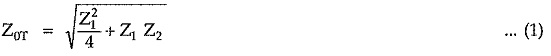
For a prototype section, the characteristic impedance is given by,
Similarly for a m-derived section, the characteristic impedance is given by,
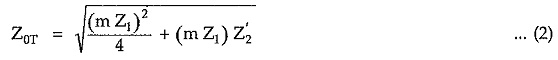
To maintain same Z0, equating equations (1) and (2) by squaring,
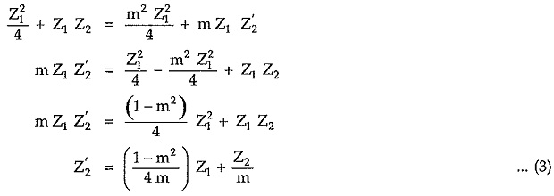
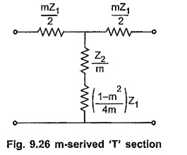
From equation (3) it is dear that, the shunt arm of m-derived section is a series connection of two impedances (Z2/m) and (1-m2/4m) Z1 if 0<m<1 as shown in the Fig. 9.26.
The same technique can be used to obtain m-derived π section. Consider any general π section with shunt arm of same type but having different value i.e. Z2/m as shown in the Fig. 9.27.
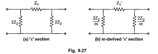
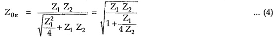
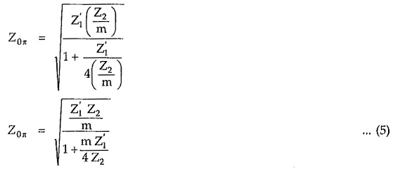
For a prototype π section, the characteristic impedance Z0π is given by,
Similarly for a m-derived π section, the characteristic impedance is given by,
Squaring equations (4) and (5) and equating,
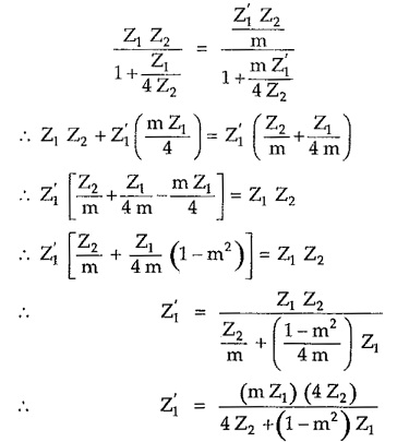
Multiplying numerator and denominator by the factor m/1-m2 we get
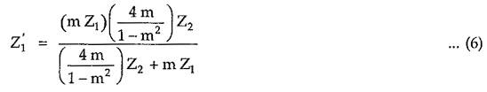
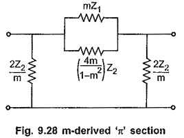
From equation (6) it is clear that, the series arm Z′1 of m-derived section is a parallel combination of two impedances (m Z1) and (4m/1-m2) Z2 with condition 0< m< 1. The m-derived π section is as shown in the Fig. 9.28.
In m-derived filters (either T or π), attenuation characteristic can be improved in stop band by using series resonant circuit formed in the shunt arm of m-derived T section and anti resonant circuit formed in the series arm of m-derived π section.
We can select a frequency of resonance of these resonant circuits such that attenuation increases very rapidly at that frequency upto ∞. Consider m-derived low pass filter. Here if frequency of resonance is selected just above
the cut-off frequency of the low pass filter, fc, the shunt arm in T section acts as a short circuit at this frequency being series resonant circuit. It short circuits the transmission path. Hence output becomes zero and attenuation increases to ∞. In π section, at frequency which is just above fc, series arm becomes open circuit being anti resonant circuit. Hence output becomes zero and attenuation increases to ∞. The frequency at which the attenuation increases to ∞ is called frequency of infinite attenuation and it is denoted by f∞. In in-derived high pass filter section, the frequency of infinite attenuation is selected just below fc, the cut-off frequency of prototype high pass filter section.
Consider the m-derived T and π sections as shown in the Fig. 9.28 and Fig. 9.30. If we put m=1, both sections reduce to corresponding prototype sections. As m is a constant, for different values of m, we can design infinite m-derived sections for same fc and z0 specifications. The shunt arm of T section is a series combination of impedances interms of Z1 and Z2 ; while series arm of π section is a parallel combination of impedances in terms of Z1 and Z2. But we know that Z1 and Z2 must be of different types. So to maintain this relationship in the shunt arm of T section and the series arm of π section, factor 1-m2/4m must be positive which gives m always positive. As we have seen earlier, for m=1, we get original prototype filter sections. Thus the value of m must be always selected as
![]()