Infinite Impulse Response Filters Interview Questions and Answers:
- The magnitude response of the Butterworth filter decreases monotonically as the frequency Ω increases from 0 to ∞.
- The magnitude response of the Butterworth filter closely approximates the ideal response as the order N increases.
- The poles of the Butterworth filter lies on a circle.
- The magnitude response of the Chebyshev filter exhibits ripple either in passband or in stopband according to type.
- The poles of the Chebyshev filter lies on an ellipse.
3. Distinguish between the frequency response of Chebyshev type I filter for N odd and N even.
Ans. The frequency response curve starts from unity for odd values of N, and starts from 1/√1+ε2 for even values of N.
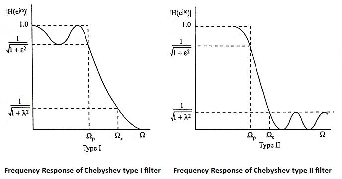
- The magnitude response of Butterworth filter decreases monotonically as the frequency Ω increases from 0 to ∞, whereas the magnitude response of the Chebyshev filter exhibits ripple in the passband and monotonically decreasing in the stopband.
- The transition band is more in Butterworth filter compared to Chebyshev filter.
- The poles of the Butterworth filter lies on a circle whereas the poles of the Chebyshev filter lies on an ellipse.
- For the same specifications the number of poles in Butterworth filter is more when compared to Chebyshev filter, i.e., the order of the Chebyshev filter is less than that of Butterworth.
- Map the desired digital filter specifications into those for an equivalent analog filter.
- Derive the analog transfer function for the analog prototype.
- Transform the transfer function of the analog prototype into an equivalent digital filter transfer function.
- Impulse invariance method
- Bilinear transformation method
- The jΩ-axis in the s-plane should map into the unit circle in the z-plane. Thus there will be a direct relationship between the two frequency variables in the two domains.
- The left half plane of the s-plane should map into the inside of the unit circle in the z-plane. Thus a stable analog filter will be converted to a stable digital filter.
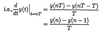
Ans. The mapping procedure between s-plane and z-plane in the method of mapping of differentials is given by
The above mapping has the following characteristics
- The left half of s-plane maps inside a circle of radius 1/2 centered at z = 1/2 in the z-plane.
- The right half of s-plane maps in to the region outsides the circle of radius 1/2 in the z-plane.
- The jΩ-axis maps on to the perimeter of the circle of radius 1/2 in the z-plane.
14. What is the matched z-transformation?
Ans. It is a method of converting an analog filter into an equivalent digital filter. Suppose that the system function of the analog filter is expressed in the factored form
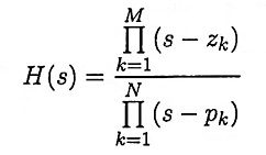
where {zk} are the zeros and {pk} are the poles of the filter. Then the system function of the digital filter is
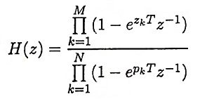
where T is the sampling interval.
15. What is meant by impulse invariant method of designing HR filter?
Ans. In this method of digitizing an analog filter, the impulse response of resulting digital filter is a sampled version of the impulse response of the analog filter.
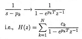
First we express the transfer function of analog filter in partial fraction form,
i.e.,
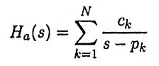
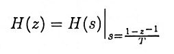
Then the transfer function of digital filter can be obtained using the transformation
16. What is warping effect? What is its effect on magnitude and phase response?
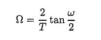
Ans. The relation between the analog and digital frequencies in bilinear transformation is given by
For smaller values of ω there exist linear relationship between ω and Ω. But for large values of ω the relationship is non-linear. This non-linearity introduces distortion in the frequency axis. This is known as warping effect. This effect compresses the magnitude and phase response at high frequencies.
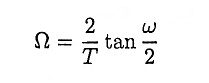
17. Write a short note on prewarping.
Ans. The effect of the non-linear compression at high frequencies can be compensated. When the desired magnitude response is piece-wise constant over frequency, this compression can be compensated by introducing a suitable prescaling, or prewarping the critical frequencies by using the formula.
18. What are the advantages and disadvantages of bilinear transformation?
Ans.
Advantages
- The bilinear transformation provides one-to-one mapping.
- Stable continuous systems can be mapped into realizable, stable digital systems. There is no aliasing.
Disadvantages
- The mapping is highly non-linear producing frequency compression at high frequencies.
- Neither the impulse response nor the phase response of the analog filter is preserved in a digital filter obtained by bilinear transformation.
19. Distinguish between recursive realization and non-recursive realization.
Ans.
- For recursive realization the present output y(n) is a function of past outputs, past and present inputs. This form corresponds to an Infinite-Impulse Response (IIR) digital filter.
- For non-recursive realizations the current output y(n) is a function of only past and present inputs. This form corresponds to an Finite Impulse Response (FIR) digital filter.
20. What are the different types of structures for realization of IIR systems?
Ans. The different types of structures for realization of IIR system are
- Direct-form I structure,
- Direct-form II structure,
- Transposed direct-form II structure,
- Cascade form structure,
- Parallel form structure,
- Lattice-ladder structure.
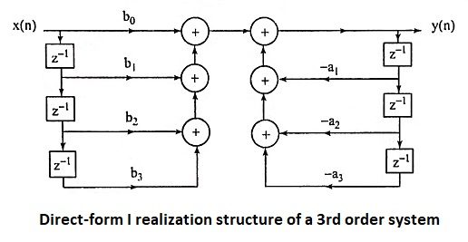
21. Draw the direct-form I realization structure of a 3rd order system.
Ans.
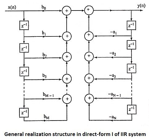
22. Draw the general realization structure in direct-form I of IIR system.
Ans.
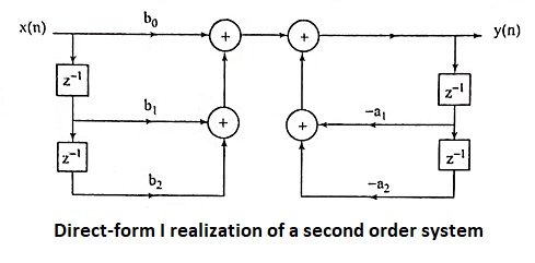
23. Give direct-form I and direct-form II structure of second order system realization.
Ans.
Direct-form I realization of a second order system
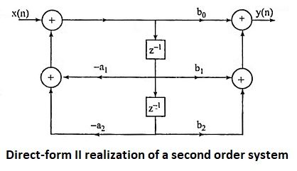
Direct-form II realization of a second order system
24. What is the main advantage of direct-form II realization when compared to direct-form I realization?
Ans. In direct-form II realization, the number of memory locations required is less than that of direct-form I realization.
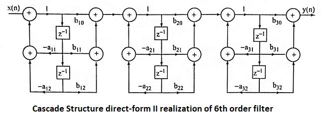
25. Draw the cascade structure direct-form II realization of 6th order filter.
Ans.
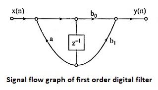
26. Define signal flow graph.
Ans. A signal flow graph is a graphical representation of the relationships between the variables of a set of linear difference equations.
27. Draw the signal flow graph of first order digital filter.
Ans.
28. What is transposition theorem and transposed structure?
Ans. The transpose of a structure is defined by the following operations.
- Reverse the directions of all branches in the signal flowgraph.
- Interchange the input and outputs.
- Reverse the roles of all nodes in the flow graph.
- Summing points become branching points.
- Branching points become summing points.
According to transposition theorem if we reverse the directions of all branch transmittance and interchange the input and output in the flowgraph, the system function remains unchanged.
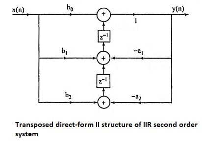
29. Give the transposed direct-form II structure of IIR second order system.
Ans.
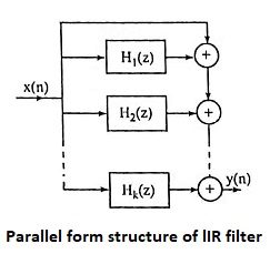
30. Draw the parallel form structure of lIR filter.
Ans.
A parallel form realization of an IIR system can be obtained by performing a partial fraction expansion of H(z).
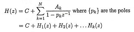
The above system can be realized in parallel form as shown in Figure.
31. What is the main disadvantage of direct-form realization?
Ans. The direct-form realization is extremely sensitive to parameter quantization. When the order of the system N is large, a small change in a filter coefficient due to parameter quantization, results in a large change in the location of the poles and zeros of the system.
32. What is the advantage of cascade realization?
Ans. Quantization errors can be minimized if we realize an LTI system in cascade form.