Composite Filters in Network Analysis:
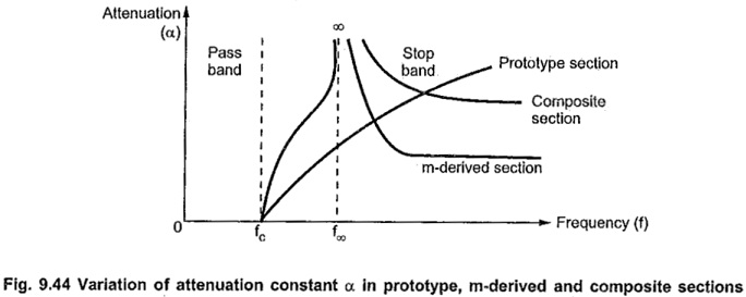
Composite Filters in Network Analysis – In prototype filter sections, the attenuation characteristic is not very sharp in the attenuation band as it is expected. This drawback can be overcome by using m-derived filter sections which are derived from respective prototype filter sections. But it is observed that in the stop band attenuation drastically reduces after f∞ in low pass section and before f∞ in high pass section. This drawback of m-derived filter can be overcome by connecting number of sections including prototype sections and m-derived sections with terminating half sections. Such a combination of different sections is called composite filter.
The comparison of attenuation constant variations in low pass prototype section, m-derived section and composite section is as shown in the Fig. 9.44.
In Composite Filters in Network Analysis, cut off frequency and the design impedance are the two important design specifications. The number of various sections in the composite filter totally depends on the attenuation characteristics required. If it is required that the attenuation should rise sharply in the attenuation band, we must select at least one m-derived section with low value of m.
In general, for lower values of m, attenuation at cut off rises rapidly. The typical value of m for such attenuation at cut off is m= 0.3 to 0.35. If it is required to maintain this attenuation at a high value in attenuation band, we must connect either a prototype section or another m-derived section with comparatively larger value of m.
If required both the sections can be used in the composite filter. To have proper impedance matching and constant characteristic impedance throughout pass band, we must connect the terminating sections with m = 0.6.
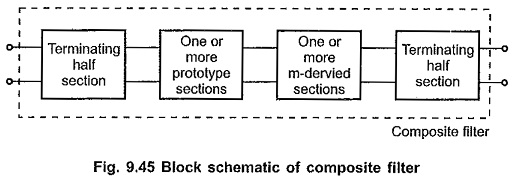
The general block schematic of the composite filter is as shown in the Fig. 9.45.