Graph Theory Network Analysis:
To analyse a network means to find current through any branch or voltage across any branch. We can analyse given network using Graph Theory Network Analysis by relating branch currents and loop currents or branch voltages and node voltages (across tree branches).
Relationship between Branch Currents and Loop Currents:
Let [Ib] represents branch current matrix and [IL] represents loop current matrix, then we can relate branch currents and loop currents as,
![]()
where [BT] is the transpose of fundamental circuit matrix [B].
When a current source is present across any branch then the total branch current will be the algebraic addition of branch current and branch input current of the source. Consider two conditions in a network as shown in the Fig. 5.17.
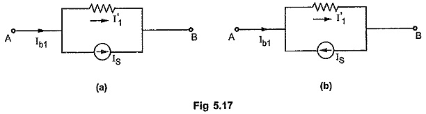
Consider Fig. 5.17 (a). The direction of the branch current and current source is same. Hence effective branch current flowing from terminal A to B is given by subtracting source current as
![]()
Consider Fig. 5.17 (b). The direction of the branch current and current source is opposite. Hence equivalent branch current flowing from terminal A to B is given by adding source current as,
![]()
In such special cases, relationship between branch currents, and loop currents can be modified in terms of source currents as follows,
![]()
where [Is] is a column matrix representing current source across each branch.
Relationship between Branch Voltages and Node Voltages:
Let [Vb] be the branch voltage matrix and [Vn] be the node voltage matrix, then we can relate branch voltage and node voltage as
![]()
where [QT] is the transpose of fundamental cut-set matrix [Q]
When a voltage source is present in series branch then the total branch voltage is the algebraic addition of source voltage and voltage across branch. Consider general conditions in any network as shown in the Fig. 5.18.
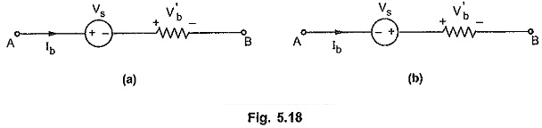
Consider Fig. 5.18 (a). If polarities of source voltage and branch voltage are same, then add source voltage and write branch voltage using sign conventions as
![]()
Consider Fig. 5.18 (b). If polarities of source voltage and branch voltage are different then subtract source voltage as
![]()
Hence in such special cases we can modify the relationship between branch voltages and node voltages in terms of source voltages as
![]()
where [Vs] represents a column matrix representing voltage sources in series with branches.
Network Equilibrium Equations on the Basis of Loop Analysis
In loop analysis, using Graph Theory Network Analysis, the minimum number of equilibrium equations required is equal to [b – (n – 1)] where ‘b’ is the number of branches and ‘n’ is the number of nodes in the graph.
Consider a circuit as shown in the Fig. 5.19 (a) and an oriented graph of it as shown in the Fig. 5.19 (b).
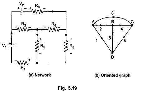
Let the branch currents in respective branches be i1, i2, i3, i4, i5 and i6 with the orientations same as those of branches. Consider a tree for oriented graph as shown in the Fig. 5.20 (a).
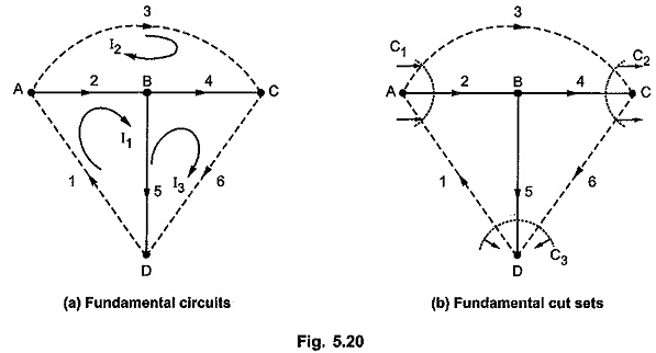
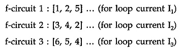
Let I1, I2 and I3 be the loop currents. The directions of loop currents are coinciding with the orientations of the links in the respective loops.
We can list f-circuits as,
Writing f-circuits in tabular form,
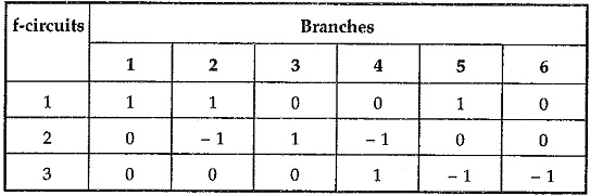
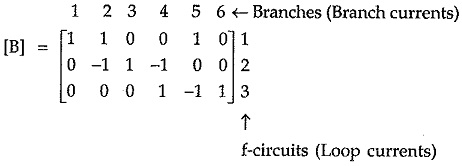
Then fundamental circuit matrix B is given by,
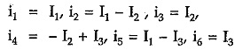
The branch currents can be expressed in terms of loop currents as
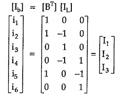
From above equation we can write,
The branch voltages can be expressed as product of branch current and branch impedance. Let v1, v2 … v6 be branch voltages.
In the first branch we have voltage source V1 in series with R1. As the polarity of voltage source and that of voltage across R1 is not same hence subtracting source voltage
![]()
In branch 2 there is no voltage source.
![]()
Again in branch 3, voltage source V2 is present. The polarities of source voltage and voltage across R3 are same hence adding source voltage.
![]()
In all remaining branches, there is no voltage source.
![]()
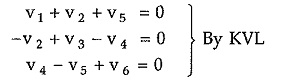
Consider fundamental circuit matrix B again. Each row in the matrix represents summation of branch voltages around fundamental circuits. Hence we can write,
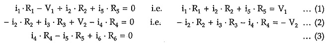
Putting values of V1, V2, V3, V4, V5 and V6 in above equations we can write,
Substituting branch currents expressed interms of the loop currents,
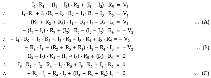
Equations (A), (B) and (C) represents equilibrium equations for the given network on the basis of loop analysis.
Network Equilibrium Equations on the Basis of Node Analysis:
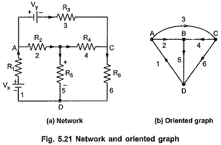
Consider Fig. 5.21. The oriented graph is as shown in Fig. 5.21. Assume the selected tree as shown in Fig. 5.22.
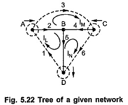
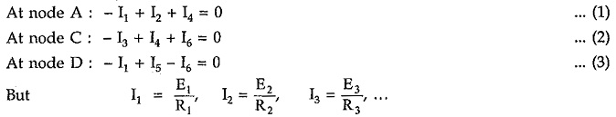
Node Analysis is based on Kirchhoff’s current law. For the given tree, we can write cut-set.
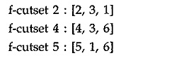
The above set of cut-set can be written in tabular form as follows :
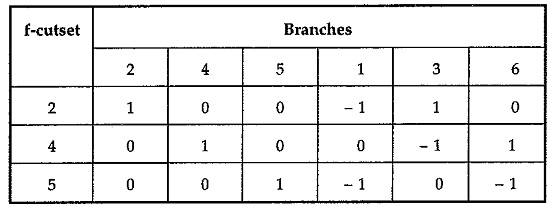
Note that in above tabular form, the elements of a column represent branch voltages and elements of the row represent branch currents.
Let branch voltages be denoted by E1, E2, E3, E4, E5 and E6. Let the voltages at nodes A, C, D be VA, VC and VD where node B is selected as datum node or reference node or zero potential node.
The branch voltages can be written as :
Branch voltage E1 (represented by column 1) = – VA – VD
Branch voltage E2 (represented by column 2) = VA
Branch voltage E3 (represented by column 3) = VA – VC
Branch voltage E4 (represented by column 4) = VC
Branch voltage E5 (represented by column 5) = VD
Branch voltage E6 (represented by column 6) = VC – VD
But for branch voltage E1 there is voltage source Vx present. Also there is voltage source Vy present in branch 3.
![]()
Also there is voltage source Vy present in branch 3.
![]()
As we have seen already, elements in a row represent a branch current and according to the Kirchhoff’s current law, the algebraic sum of the currents at any node is always zero, we can add all the elements of each row to get zero current at that node.
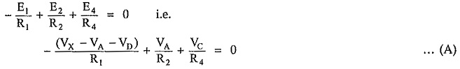
Substituting all these values in above equations, we have
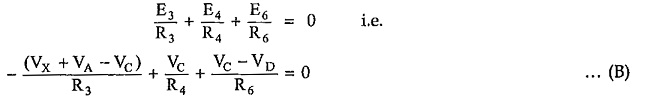
The second equation can be written as,
The third equation can be written as,
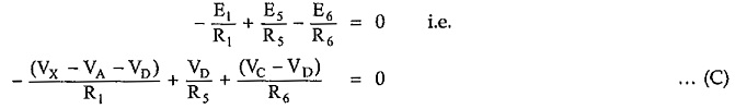
The branch voltages E1, E2, E3, E4, E5 and E6 can be expressed in terms of node pair voltages VA, VC and VD.
Thus equations (A), (B), (C) will then become three independent equilibrium equations in terms of variables VA, VC and VD.
Then by solving all these equation simultaneously, we can get values of node voltages, branch voltages and branch currents.