Attenuators in Network Analysis:
In various transmission equipments, it is many times required to supress or reduce the levels of the currents and voltages at certain points. To fulfill the need of attenuation, a four terminal resistive network called attenuator is used. Attenuators in Network Analysis are designed to provide a known amount of attenuation between input and output terminals without changing the matching of the impedance at a given value. Attenuators are resistive networks, so all frequencies are attenuated by same degree of amount preventing attenuation distortion. As all the components are resistive in the attenuator networks, no phase shift will be introduced by such networks. Hence the phase constant (β) will be zero and the propagation constant (γ) will be equal to only the attenuation constant (α).
Attenuators in Network Analysis are either symmetrical or asymmetrical networks. Attenuators are either of fixed value or adjustable value type. Generally fixed attenuators providing constant attenuation are called pads. The variable attenuators are generally used in radio broadcasting stations as volume controls. Attenuation is usually expressed in neper or decibel.
Power Ratios, Voltage Ratios and Current Ratios:
In line communication, when AC power from one point (generally sending end) to another point (generally receiving end) is considered, various elements in the communication system introduce gains or losses of power at various points.
Consider a four terminal network between a generator and a load as shown in the Fig. 10.1.
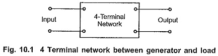
Let input and output powers be P1 and P2 respectively. The network introduced in between generator and load may provide loss or gain in power. Let the ratio of input power to output power i.e. P1/P2 be M.
If M is greater than unity, then the network introduces loss. If M is less than unity, then the network introduces gain.
If ‘n’ number of such networks are connected in cascade or tandem, then the overall power ratio of cascade connection can be obtained by multiplying individual power ratios of networks.
Let M1 to Mn-1 be individual input power to output power ratios for (n —1) number of networks respectively connected in cascade. Then overall power ratio M can be written as,
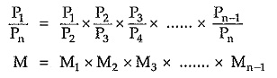
From above expression it is clear that in the complex systems, calculation of overall power ratio is very tedious. To simplify this calculation the individual power ratios are expressed in logarithmic scale. This enables addition of power ratios in the logarithmic scale instead of multiplication. The logarithmic unit employed is “BELL”.
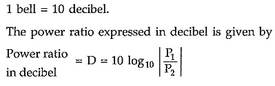
Hence, we can express power ratio in bell as follows,
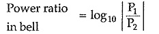
But in practice, it is observed that the unit bell is too large. Hence instead of bell a smaller unit called as decibel is introduced, where,
Thus, if ratio (P1/P2) is greater than unity, then D will be positive which indicates power loss. Similarly if ratio (P1/P2) less than unity, then D will be negative which indicates power gain.
The power ratio can be expressed in decibel as follows,
![]()
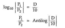
Thus using this conversion we can express any power (either input or output) in watt.
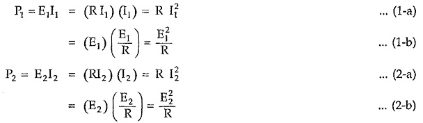
Consider again the network shown in the Fig. 10.1. Assume that two equal resistors of value R are connected at generator and load side. Let the current and voltage at source side be I1 and E1 and current and voltage at load side be I2 and E2. The power developed across resistors at source and load side can be written as,
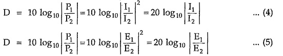
Then input to output power ratio can be given by

Expressing all the ratios in decibel as follows,
Expression of Attenuation in Neper and Decibel:
Attenuation is defined as loss of power in a transmission line or an electrical network. Attenuation is expressed either in neper (N) or decibel (dB) notations.
Usually power ratios are expressed in decibel. But it is possible to express voltage and current ratios in decibel if the resistive components of generator and load impedances are equal.
Similarly neper is usually used to express current ratios. But it is possible to express power ratio in neper if the resistive components of generator and load impedances are equal.
Consider a four terminal network as shown in the Fig. 10.2 between generator and load.
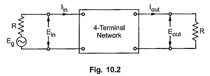
If the power entering a network is Pin and that leaving the network is Pout, then the attenuation in decibel is defined as,
![]()
If the current entering a network is Iin and that leaving the network is Iout, then the attenuation in neper is defined as,

Under the condition of equal resistive components at generator and load side, we can write,
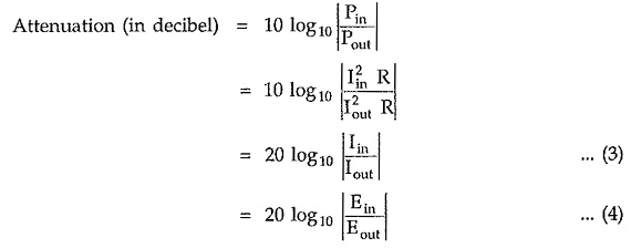
Similarly,
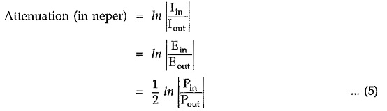
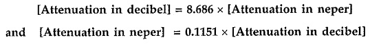
If the resistive components of the impedances at input (i.e. generator) and output (i.e. load) of the network are equal, we can convert attenuation in any notation as follows