First Order High Pass Butterworth Filter:
As mentioned earlier, a high pass filter is a circuit that attenuates all the signals below a specified cut off frequency denoted as fL. Thus, a high pass filter performs the opposite function to that of low pass filter. Hence, the First Order High Pass Butterworth Filter circuit can be obtained by interchanging frequency determining resistances and capacitors in low pass filter circuit.
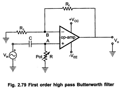
The first order high pass filter can be obtained by interchanging the elements R and C in a first order low pass filter circuit. The Fig. 2.79 shows the first order high pass Butterworth filter.
It can be observed that as compared to first order low pass filter, the positions of R and C are changed in the high pass circuit shown in Fig. 2.79.
The frequency at which the gain is 0.707 times the gain of filter in pass band is called as low cut off frequency and denoted as fL. So, all the frequencies greater than fL are allowed to pass but the maximum frequency which is allowed to pass is determined by the closed loop bandwidth of the op-amp used.
Analysis of the Filter Circuit:
The impedance of the capacitor is
![]()
where f is the input i.e. operating frequency.
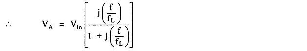
By the voltage divider rule, the potential of the non inverting terminal of the op-amp is
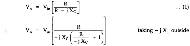
As
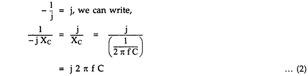
Substituting in the above expression of VA,.
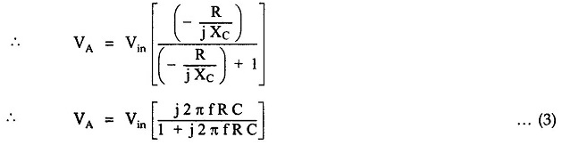
This can be represented as
where
![]()
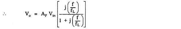
Now, for the op-amp in non-inverting configuration,
![]()
where
![]()
and

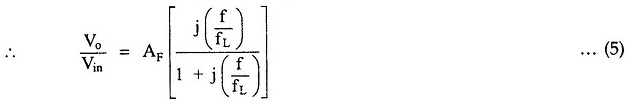
This is the required expression for the transfer function of the filter. For the frequency response, we require the magnitude of the transfer function which is given by,
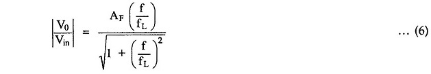
The equation (6) describes the behavior of the high pass filter.
1.At low frequencies, i.e. f < f′L

2) At f < f′L

3) At f > fL, i.e. high frequencies, 1 can be neglected as compared to (f/fL) from denominator.

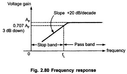
Thus, the circuit acts as high pass filter with a passband gain as AF. For the frequencies, f < fL, the gain increases till f = fL at a rate of + 20 dB/decade. Hence, the slope of the frequency response in stop band is + 20 dB/decade for first order high pass filter. The frequency response is shown in the Fig. 2.80.
Note : As high pass filter is basically a low pass filter circuit with positions of R and C interchanged, the design steps and the frequency scaling method discussed earlier for low pass filter is equally applicable to the first order high pass Butterworth filter.