Low Pass Filter Circuits:
The Low Pass Filter Circuits of Fig. 15.7 is commonly used for low pass active filters. The filtering is done by the use of an RC network. The opamp is used as a unity gain amplifier. The resistor RF is equal to R1.
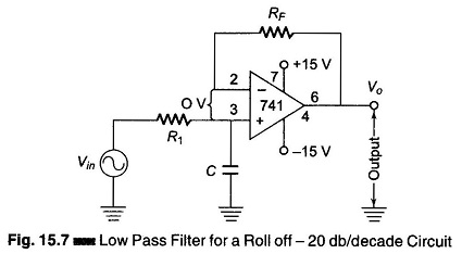
(At dc, the capacitive reactance is infinite and the dc resistance path to ground for both input terminals must be equal.) The difference voltage between inverting and non-inverting inputs is essentially O V. Hence, the voltage across the capacitor C equals the output voltage. Since this circuit is a voltage follower, Vin divides between R and C. The capacitor voltage Vo is given by

where ω is the frequency of Vin in radians per second (ω = 2 πf and j is the imaginary term. To obtain the closed loop voltage gain ACL, we have,
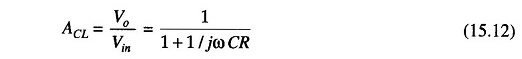
Consider the Eq. (15.12). At very low frequencies, as ω approaches 0, | ACL | = 1, and at very high frequencies, as ω approaches infinity, | ACL | = 0. Hence this filter is a Low Pass Filter Circuits.
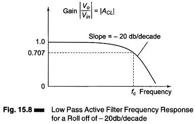
Figure 15.8 shows a frequency response of ω versus | ACL |. For frequencies greater than the cutoff frequency ωc, | ACL | decreases at a rate of 20 db/decade. This is the same as saying that the voltage gain is divided by 10 when the frequency of ω is increased by 10.
The cutoff frequency is defined as that frequency of Vin where | ACL | is reduced to 0.707 times its low frequency value. The cutoff frequency is calculated from
![]()
Therefore,

Where
- fc = is the cutoff frequency in Hz
- R = resistance in Ω
- C = capacitance in Farad.
The Eq. (15.13) can be rearranged to solve R, ignore to give