Second Order Low Pass Butterworth Filter:
The practical response of Second Order Low Pass Butterworth Filter must be very close to an ideal one. In case of low pass filter, it is always desirable that the gain rolls off very fast after the cut off frequency, in the stop band. In case of first order filter, it rolls off at a rate of 20 dB/decade. In case of second order filter, the gain rolls off at a rate of 40 dB/decade. Thus, the slope of the frequency response after f = fH is — 40 dB/decade, for a second order low pass filter.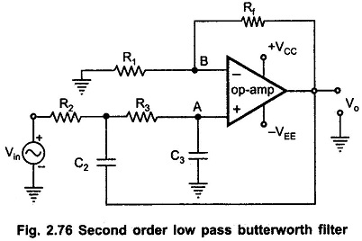
A first order filter can be converted to second order type by using an additional RC network as shown in the Fig. 2.76. The cut off frequency fH for the filter is now decided by R2, C2, R3 and C3. The gain of the filter is as usual decided by op-amp i.e. the resistance R1 and Rf.
Analysis of the Filter Circuit:
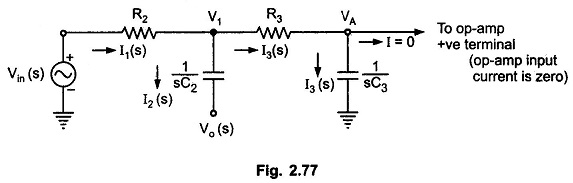
For deriving the expression for the cut off frequency, let us use the Laplace transform method. The input RC network can be represented in the Laplace domain as shown in Fig. 2.77.
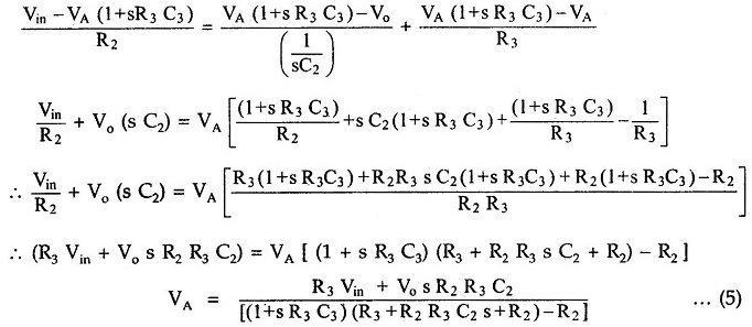
Now
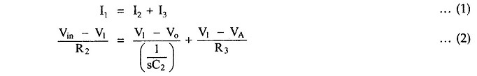
Using potential divider rule, we can Write
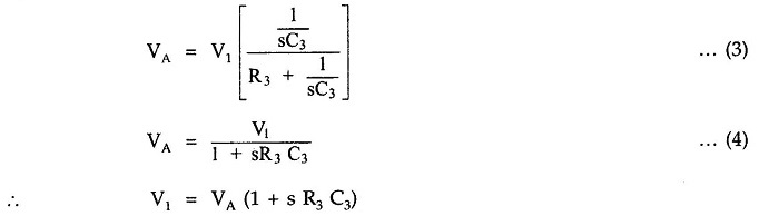
Substituting in (1) and solving for VA, we get
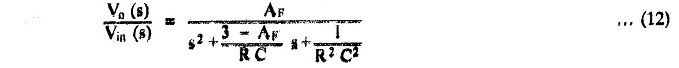
Now, for op-amp in noninverting configuration,
![]()
where
![]()
and
![]()
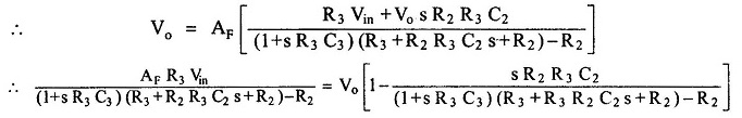
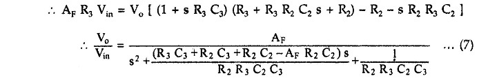
As the order of s in the gain expression is two, the filter is called Second Order Low Pass Butterworth Filter.
Second Order Butterworth Filter Transfer Function:
The standard form of Second Order Butterworth Filter Transfer Function of any second order system is
![]()
where
- A = overall gain
- ξ = damping of system
- ωn = natural frequency of oscillations
Comparing (7) and (8), we can say that
![]()
In case of Second Order Low Pass Butterworth Filter, this frequency is nothing but the cut-off frequency, ωH
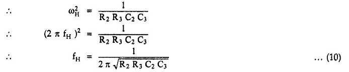
This is the required cut off frequency.
Replacing s by jω, the transfer function can be written in the frequency domain and hence, finally, can be expressed in the polar form as,

where
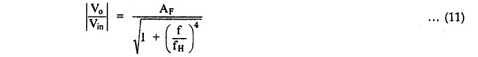
and
- AF = gain in filter in pass band
- f = input frequency in Hz
- fH = high cut-off frequency in Hz
The frequency response is shown in Fig. 2.78.
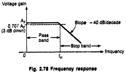
At the cut off frequency fH, the gain is 0,707 AF i,e. 3 dB down from its 0 Hz level. After, fH ( f > fH ), the gain rolls off at a frequency rate of 40 dB/decade,. Hence, the slope of the response after fH is – 40 dB/decade.
Design Steps:
The design steps for Second Order Low Pass Butterworth Filter are
1) Choose the cut-off frequency fH,
2) The design can be simplified by selecting R2 = R3 = R and C2 = C3 = C and choose a value of C less than or equal to 1 μF.
3) Calculate the value of R from the equation,

4) As R2 = R3 = R and C2 = C3 = C, the pass band voltage gain AF = (1 + Rf/R1) of the second order low pass filter has to be equal to 1.586.
Note: For R2 = R3 = R and C2 = C3 = C, the transfer function takes the form
From this we can write that,
![]()
Now, for Second Order Low Pass Butterworth Filter, the damping factor required is 0.707, from the normalized Butterworth polynomial.
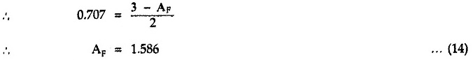
Thus, to ensure the Butterworth response, it is necessary that the gain Af is 1.586.

![]()
Hence, choose a value of R1 ≤ 100 kΩ and calculate the corresponding value of Rf.
The frequency scaling method discussed earlier for first order filter is equally applicable to the Second Order Low Pass Butterworth Filter