Various Bias Compensation Methods:
During the discussion made for various biasing methods for providing stability to the operating point we have seen that self bias (or potential divider bias) and collector-to-base bias circuits provide better operating point stability but in both arrangements the stabilization is provided due to negative feedback action of the circuit. Although the negative feedback improves the operating point stability but it also reduces drastically the amplification of the signal. In certain applications, the loss in the signal gain may be intolerable and in such cases it is better to use Bias Compensation techniques in order to reduce the drift of the operating point. Sometimes both stabilization and bias compensation techniques are used for providing excellent bias and thermal stabilization. In Bias Compensation Methods temperature-sensitive devices such as diodes, transistors, thermistors, sensistors etc. are used to provide compensation for variations in currents.
Diode Compensation For Variations in Base-Emitter Voltage VBE
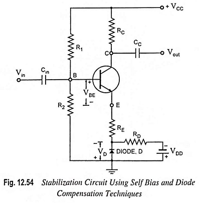
A circuit utilizing the self-bias stabilization and diode compensation is shown in Fig. 12.54. The Thevenin’s equivalent circuit is given in Fig. 12.55. The diode is kept forward biased by the source VDD and resistor RD. The diode employed is of the same material and type as the transistor and as a consequence the voltage across the diode has the same temperature coefficient (-2.5 mV per °C) as VBE of the transistor.
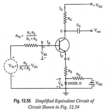
Applying Kirchhoff’s voltage law to the base portion of the circuit shown in Fig. 12.55, we have
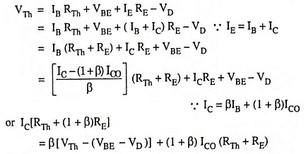
or Collector current,
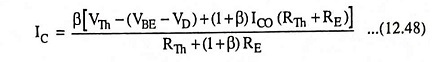
Since variations in VBE and VD are the same due to temperature variation, so (VBE – VD) remains unchanged in above Eq. (12.48) and collector current IC, therefore, becomes insensitive to variations in VBE. In practice, the compensation of VBE as explained above is not perfect but it is sufficiently effective to take care of a great part of transistor drift due to variations in VBE.
Diode Compensation For Variations in ICO
We have seen that in silicon transistors the variations in base-emitter voltage VBE due to temperature variations contribute significantly towards collector current variations. On the other hand, in case of germanium transistors, changes in reverse saturation current ICO with temperature variations result in more serious problem in collector current stability. The circuit using diode compensation for a germanium transistor amplifier is given in Fig. 12.56. The diode D used in circuit is of the same material and type as the transistor. So the reverse saturation current of transistor ICO and that of the diode, I0 will increase at the same rate with the increase in temperature.
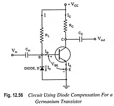
From circuit diagram shown in Fig. 12.56.
Since diode is reverse biased by base-emitter voltage VBE (0.3 V in case of Ge transistor), the current through diode is the reverse saturation current I0.
Now base current IB = I – I0
Substituting IB = (I – I0) in equation of collector current,
IC = βIB + (1 + β)ICO, we have
Collector Current,
![]()
From Eq. (12.49) it is obvious that if β ≫ 1 and if I0 of diode and ICO of transistor track each other over the desired temperature range, then collector current IC remains essentially constant.
Thermistor Compensation:
Circuit using thermistor compensation in a self-bias CE amplifier is shown in Fig. 12.57. The thermistor RT has a negative temperature coefficient of resistance (resistance decreasing exponentially with increasing temperature T). The thermistor RT is used in the circuit to minimize the increase in collector current due to variations in ICO, VBE or β with temperature. With the increase in temperature, the resistance of the thermistor decreases and consequently current supplied to the emitter resistance RE through RT increases. The voltage drop across emitter resistance RE is in the direction to reverse bias the transistor. Thus the temperature sensitivity of RT acts as to compensate the increase in collector current IC due to rise in temperature T and therefore, collector current IC remains constant.
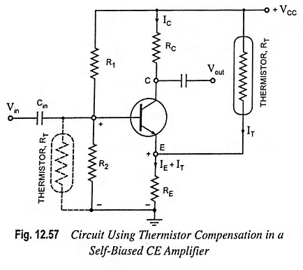
The thermistor can also be placed, as an alternative, in the base circuit across R2 instead of in collector circuit, as shown dotted in the Fig. 12.57. With the increase in temperature T, voltage drop across RT decreases and thus the forward-biasing base voltage decreases. As a result collector current IC decreases and thus increase in lC due to increase in temperature is compensated for.
Sensistor Compensation:
Instead of a thermistor, it is possible to use a temperature-sensitive resistor with a positive temperature coefficient such as metal or sensistor. The sensistor has a temperature coefficient of resistance of 0.007 per °C (over the range from – 60°C to 150°C). Sensistor is a heavily doped semiconductor. The sensistor may be placed either in parallel with R1, as illustrated in Fig. 12.58 or in parallel with RE, as shown dotted in Fig. 12.58. Sensistor can also be placed in place of RE rather than in parallel with RE. With the increase in temperature, the resistance of the sensistor RS increases and so the resistance of parallel combination (RS || R1). As a result the voltage drop across R2 decreases thereby decreasing the net forward emitter bias. Thus collector current IC decreases compensating increase in collector current due to increase in ICO, β or VBE because of temperature rise.
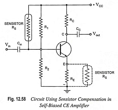
The same result is obtained if the sensistor RS is placed in parallel with (or in place of) emitter resistor RE.