Various CRT Connections and Controls in CRO Panel:
Figure 7.16 shows various controls and Typical CRT Connections. The following controls are available on CRO panel.
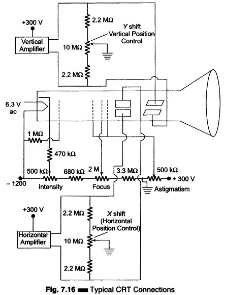
Intensity:
It controls the magnitude of emission of the electron, beam, i.e. the electron beam is adjusted by varying the cathode-to-grid bias voltage. This adjustment is (folk by the 500 KΩ potentiometer
Focus:
The focusing anode potential is adjusted with respect to the first and final accelerating anodes. This is done by the 2 MΩ It adjusts the negative voltage on the focus ring between -500 V and -900 V.
Astigmatism:
It adjusts the voltage on the acceleration anode with respect to the VDP of the CRT. This arrangement forms a cylindrical lens that corrects any defocusing that might be present. This adjustment is made to obtain the roundest spot on the screen.
X-shift or Horizontal Position Control:
The X-position of the spot is adjusted by varying the voltage between the horizontal plates. When the spot is in the centre position, the two horizontal plates have the same
Y-shift or Vertical Position Control:
The X-position of the spot is adjusted by varying the voltage between the vertical plates. When the spot is in the centre position, the two vertical plates have the same potential.
Time Base Control:
This is obtained by varying the CT and RT of the time base generator.
Sync Selector:
It can synchronise the sweep to signals coming internally from the vertical amplifier or an external signal or the line supply Int Ext-Line switch.