What is Cathode Ray Tube (CRT) of an Oscilloscope?:
What is Cathode Ray Tube (CRT) of an Oscilloscope? – To understand the principle of an Electron Beam Experiment in CRT, let us consider a torch which is focused on a piece of cardboard (held perpendicular to the torch). The light beam will make a bright spot where it strikes the cardboard or screen. Hold the torch still, the spot remains still, move the torch, the spot also moves. If the movement is slow, the eye can follow the movement, but if it is too fast for the eye to follow, persistence of vision causes the eye to see the pattern traced by the spot. Hence when we wave the torch from side to side, a horizontal line is traced; we can similarly have a vertical line or a circle. Hence, if the torch is moved in any manner at a very rapid rate, light would be traced, just like drawing or writing.
A similar action takes place in the Cathode Ray Tube of an oscilloscope. The torch is replaced by an electron gun, the light beam by a narrow Electron Beam Experiment in CRT, and the cardboard by the external flat end of a glass tube, which is chemically coated to form a fluorescent screen. Here the electron gun generates the beam which moves down the tube and strikes the screen. The screen glows at the point of collision, producing a bright spot.
When the beam is deflected by means of an electric or magnetic field, the spot moves accordingly and traces out a pattern. The electron gun assembly consists of the indirectly heated cathode with its heater, the control grid, and the first and second anodes.
The control grid in the Cathode Ray Tube is cylindrical, with a small aperture in line with the cathode. The electrons emitted from the cathode emerge from this aperture as a slightly divergent beam. The negative bias voltage applied to the grid, controls the beam current. The intensity (or brightness) of the phosphorescent spot depends on the beam current. Hence this control grid bias knob is called or labelled as intensity.
The diverging beam of electrons is converged and focused on the screen by two accelerating anodes, which form an electronic lens. Further ahead of the grid cylinder is another narrow cylinder, the first anode. It is kept highly positive with respect to the cathode. The second anode is a wider cylinder following the first. Both the cylinders have narrow apertures in line with the Electron Beam Experiment in CRT. The second anode is operated at a still higher positive potential and does most of the acceleration of the beam. The combination of the first anode cylinder and the wider second anode cylinder produces an electric field that focuses the electron beam on the screen, as a lens converges a diverging beam of light.
The electronic lens action is controlled by the focus control. If this control is turned to either side of its correct focusing position, the spot on the screen becomes larger and blurred. Bringing it back to its correct position brightens and concentrates the spot. With this proper focus, the small spot can be deflected to produce sharp narrow lines that trace the pattern on the Cathode Ray Tube screen.
The Electron Beam Experiment in Cathode Ray Tube may be deflected transversely by means of an electric field (electrostatic deflection) or a magnetic field (electromagnetic deflection).
Most oscilloscopes use electrostatic deflection, since it permits high frequency operation and requires negligible power. Electromagnetic deflection is most common in TV picture tubes.
Electrons are negatively charged particles, they are attracted by a positive charge or field and repelled by a negative charge. Since the electron beam is a stream of electrons, a positive field will divert it in one direction and a negative field in the opposite direction. To move the beam in this way in the CRT, deflecting plates are mounted inside the tube and suitable deflecting voltages are applied to them.
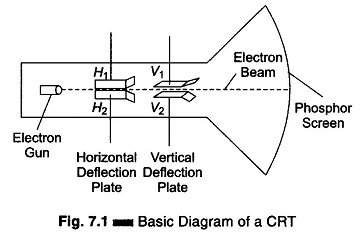
These plates are arranged in two pairs; H1 and H2 for deflecting the beam horizontally, and V1 and V2 for deflecting it vertically. Leads are taken out for external connections. The beam passes down the tube between the four plates, as shown in Fig. 7.1.
When the plates are at zero voltage the beam is midway between them and the spot is in the centre of the screen. When H1 is made positive with respect to the cathode (and all other plates are at zero voltage), it attracts the beam and the spot moves horizontally to the left. When H2 is made positive, it attracts the beam and the spot moves horizontally to the right. Similarly when V1 is made positive, the spot moves vertically upwards and when V2 is made positive it moves vertically downwards. In each of these deflections, the displacement of the beam, and therefore, the distance traveled by the spot, is proportional to the voltage applied at the plates.
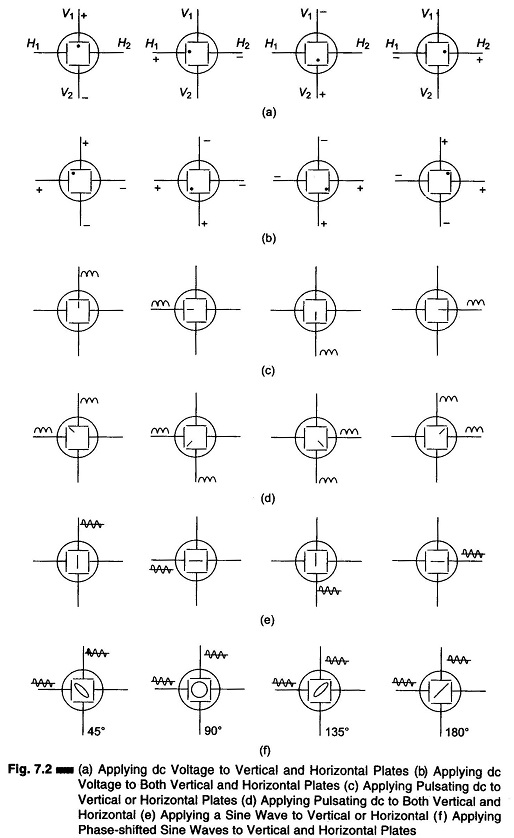
Figure 7.2 shows the various positions of the Electron Beam Experiment in Cathode Ray Tube for different voltages applied to the two pairs of plates. If a negative voltage is applied to any plate, the beam will be repelled rather than attracted and the deflection will be in the opposite direction. For example, if V1 is made negative, the beam will be deflected vertically downward.
As mentioned before, when a spot moves too rapidly for the eye to follow it traces a line. The same happens when a rapidly pulsating or ac voltage is applied to the deflecting plates, the beam is moved back and forth so rapidly that the spot traces a line. When a positive pulsating voltage is applied to H1 (or negative pulsating to H2) the spot traces a horizontal line from the centre to the left. Similarly when a positive pulsating voltage is applied to H2 (or negative to H1), the spot traces a horizontal line from the centre to the right. Similarly, when the pulsating voltage is applied to V1, we get a vertical line from the centre upwards and when applied to V2, we get a vertical line from the centre downwards.
Now, when an alternating voltage is applied to H1 or H2, the spot moves from the centre to one side, back to the centre and on to the other side, back again and so on, tracing a line that passes through the centre of the screen (because of the attraction and repulsion of the beam by the positive and negative ac half cycles). Hence, a horizontal line is traced when an ac voltage is applied to either horizontal plates. Similarly, a vertical line is traced when an ac voltage is applied to the vertical plates.
Now, let us see what happens to the beam when voltage is applied simultaneously to both vertical and horizontal plates.
When voltage is applied to the vertical and horizontal plates simultaneously, the deflection of the beam is proportional to the resultant of the two voltages and the position of the beam is in between the horizontal and vertical axis of the screen.
Suppose a steady voltage is applied to one horizontal and one vertical plate. When these two deflection voltages are equal, the position of the spot is 45°. The angle is greater than 45° (spot close to V-axis) when the vertical voltage is greater than the horizontal, and less than 45° (spot close to the H-axis) when the horizontal voltage is greater than the vertical voltage. When the two voltages are reversed in polarity, the deflection is in the opposite direction.
If instead of a steady voltage a pulsating positive voltage is applied to the same plates as before, a tilt of 45° is obtained from the horizontal if the two voltages are equal and in phase. The tilt is greater than 45° if the vertical voltage is greater than the horizontal voltage, and less than 45° if the horizontal voltage is greater than the vertical voltage. When a negative voltage is applied to both plates, the trace extends in the opposite direction. When an alternating voltage in phase is applied to the plates, the tilt of the trace is 45° from the horizontal when the two voltages are equal, it traces a straight line at an angle of 45 degrees. Again the tilt is greater than 45° if the vertical voltage is greater, and less than 45° if the horizontal voltage is greater.
The ac trace has equal length from the centre of screen to either tip, when the ac is symmetrical. When it is asymmetrical, the shorter part corresponds to the lower voltage half cycle.
A single trace is obtained only when the phase angles are 0°, 180°, or 360°. At other phase angles a double line trace is obtained at equal voltages, the pattern becomes an ellipse with a right tilt for angle between 0-90°, a circle at 90° and an ellipse with a left tilt between 90-180°. Again, a left tilt between 180-270°, a circle at 270°, an ellipse with lift tilt between 270-360°.