Color Picture Tube Working:
A Color Picture Tube Working requires correct sweep currents, input voltages and drive voltages. Having said this very quickly, it is now a good idea to examine the circuit block of Figure 17-23, to gauge the complexity of those requirements. The Color Picture Tube Working has three cathodes, or electron guns; they may be in-line or in a delta formation. It is the function of each cathode to produce an electron beam which, having been affected by various voltages and magnetic fields along its path, eventually reaches the correct part of the screen at precisely the right time. The main difference between this tube and a monochrome tube is that three beams are formed, instead of just one.
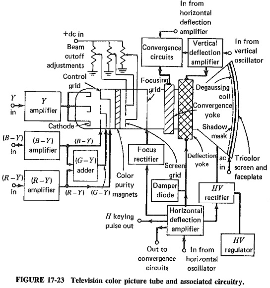
Some color TV receivers, such as the one whose partial block is shown in Figure 17-23, use the Color Picture Tube Working as a matrix. In others, voltages fed to each of the three hue amplifiers correspond to the pure primary colors, blue, green and red. In the receiver type shown, the output of the color demodulators has two channel, with voltages corresponding to (B — Y) provided in one of the channels, while the other channel provides (R — Y). The next section will show how and why these two signals are obtained. Each of the signals is amplified separately, and they are then added in the correct proportions to produce the (G — Y) video voltages. Reference to the color vector disk show that, as a good approximation, the vector addition of -0.5R and -0.2B produces the G vector. If the same voltage, Y, is subtracted from all three, the relationship still holds, and we have
![]()
The (G — Y) adder of Figure 17-23 performs the function of Equation (17-4). The three primary color voltages (with the luminance voltage, Y, subtracted from each) are now applied to their respective grids, as shown in Figure 17-23. There is a potentiometer in each path (not shown), to provide adjustment ensuring that the three drive voltages have the correct amplitudes.
If this were not done, one of the colors on the screen could predominate over the others.
In a monochrome transmission, all three grid voltages would be zero, and the only voltage then modulating the beam currents would be the -Y luminance signal applied to all three cathodes in parallel. In a color transmission, the four drive voltages will all be produced. The luminance signal applied to the cathodes will add to each of the grid voltages, cancelling the Y component of each and ensuring that only the R, G or B video voltages modulate the respective beams from this point onward. Note that usual 180° phase reversal between grid and cathode takes place here also. The -Y voltage applied to the cathodes is equivalent to +Y at a grid, and addition does take place.
The three beams now pass the color purity magnets. These are small, adjustable permanent magnets, which have the task of ensuring that each resultant color is as pure as possible. Adjustment is made to produce minimum interference between the beams.
The next port of call for the beam is a series of three screen grids. Aside from accelerating the beam, as in any other vacuum tube, these screen grids have a very important function. Each is connected to a positive dc voltage via a potentiometer,. which is adjusted to give the same cutoff characteristic for each beam. There will be the same input-voltage-beam-current relationship for the small-drive nonlinear portion of each electron gun’s operating region. This is necessary to ensure that one beam does not predominate over the others in this low-drive portion of the curve. Otherwise white could not be obtained at low light levels. Control of the cutoff characteristics at the screen grid is convenient and common.
It is then necessary to focus each beam, so that it has the correct small diameter. This ensures that fineness of detail is obtainable, like painting a canvas with a fine brush. Focusing is performed with an electrostatic lens, in the form of a grid to which a dc potential of about 5 kV is applied. The current requirement is very low, so that it is possible to obtain the focusing voltage by rectifying the flyback pulse in the horizontal output stage. The operation of the focus rectifier is identical to that of the HV rectifier in monochrome receivers.
We must now switch our attention to the color screen end of the Color Picture Tube Working. This is a large glass surface with a very large number of phosphor dots on it. Three types of medium-persistence phosphor are used, one for each of the three colors. Dots (or sometimes small stripes) of one of the phosphors will glow red when struck by the beam from the “red gun,” with an intensity depending on the instantaneous beam current. Dots of the second phosphor will similarly glow green, and those of the third will glow blue. The dots are distributed uniformly all over the screen, in triplets, so that under a powerful magnifying glass one would see three adjacent dots, then a small space, three more adjacent dots, and so on. A correct Color Picture Tube Working is obtained if the beam for each gun is able to strike only the dots that belong to it. Students will appreciate what an unreal picture would be obtained if, for example, the beam from the “blue gun” were able to strike phosphor dots which could glow green or red.
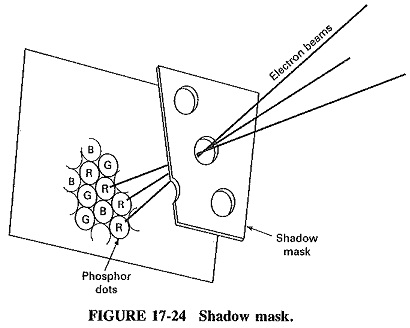
The shadow mask is used to ensure that a beam strikes only the appropriate phosphor dots on the screen (see Figure 17-24). It is a thin metal plate with about 200,000 small holes, corresponding to the (approximately) 200,000 screen dots of each color. The holes, or slots, in the shadow mask are arranged so that there is one of them for each adjacent trio of phosphor dots (or stripes). Since each beam strikes from a slightly different angle, it is possible to position the shadow mask so that each beam can strike only the correct dots.
The shadow mask is bonded into place during the manufacture of the tube, so there is no question of adjusting it to ensure correct physical alignment. Any adjustments that are performed during the lineup of the receiver must be on the beams themselves. The process is known as adjustment of the Convergence. It is performed with the convergence yoke, situated just before the deflection yoke as shown in Figure 17-23. The convergence yoke has a set of three coils, each with its own permanent magnet, which is adjustable. Convergence for the Undeflected Beam, or Static Convergence, is obtained by adjusting the permanent magnets. Dynamic Convergence, when the beam is being deflected, is provided by varying the currents through the convergence coils. These currents are derived from the horizontal and vertical deflection amplifiers.
The beams, now more than halfway to the screen, then encounter the vertical and horizontal coils in the deflection yoke. What happens then is exactly what happened at the corresponding point in a monochrome receiver, except that here three beams are simultaneously deflected, whereas previously there had been only one beam. The methods of providing the requisite deflection currents are also as already described.
It is worth mentioning at this point that most Color Picture Tube Working now, like their monochrome counterparts for some time, have deflections of the order of 110°, whereas these previously had been 90°. This deflection, it will be recalled, is given as the total corner-to-corner figure, and it corresponds to 55° beam deflection away from center, when the beam is in one of the four corners of the Color Picture Tube Working. The greater the deflection, the shorter need the tube be.
Since the length of the Color Picture Tube Working determines the depth of the cabinet, large deflection is advantageous. It does have the disadvantage of requiring greater deflection currents, since more work must be done on the beams to deflect them 55° from center, instead of 45°. The problem is somewhat alleviated by making the 110° deflection tube with a narrower neck, so that the deflection coils are closer to the beams themselves. The magnetic field can be made more intense over the smaller area.
The shadow mask, through which the beams now pass, ensures that the correct dots are activated by the right beams, but it also produced three side effects. The first is a reduction in the number of electrons that hit the screen. This results in reduced brightness but is compensated by the use of a higher anode voltage. Color tubes require typically 25 kV for the anode, where monochrome tubes needed about 18 kV. In hybrid receivers the higher voltage is obtained by having a larger overwind in the horizontal output transformer, and a rectifier with an appropriately higher rating. In solid-state receivers an additional winding is often used for this purpose, with silicon diodes in a doubling or tripling rectifier configuration. Because color tubes are rather sensitive to anode voltage variations, this voltage is regulated.
Those electrons that do not hit the screen quite obviously hit the shadow mask. With the high anode accelerating voltage, such electrons are traveling at Relativistic Velocities (i.e., at velocities sufficiently appreciable when compared with the velocity of light that relativity cannot be entirely ignored). When striking the shadow mask, these electrons are liable to produce x-ray emissions from the steel in it. This is problem number two. It is not a very serious one, because the soft (low-energy) x-rays emitted are stopped by most solid materials. A metal hood around the picture tube is sometimes used to contain the x-rays, but the aquadag coating is generally sufficient. With a properly constructed faceplate, the radiation is negligible unless the anode voltage exceeds the design value. Receivers generally have a circuit designed to disable the horizontal output stage (where this voltage is generated) if anode voltage becomes excessive. Health authorities set limits on the maximum permissible radiation for color TV receivers.
The third problem results from the presence of large metallic areas, especially the shadow mask, near the screen of the picture tube. These can become permanently magnetized by the earth’s magnetic field, producing a local magnetic field which can deflect the beam. Such a spurious deflection may not be very large, but even so it is likely to affect the convergence. The standard method used for demagnetization, or degaussing, is the application of a gradually reducing ac magnetic field. This explains the presence of the Degaussing Coil around the rim of the picture tube near the screen. A spiral coil is used, and has the mains ac voltage applied to it when the set is switched on. This takes place automatically, and a thermistor is used in such a way that the current soon decays and eventually drops to zero. Meanwhile the tube has been degaussed, in more or less the time it takes to warm up. The coil is shielded for safety.