Color Bar Generator:
The composite video signal at the output of a video detector consists of luminance Y signals, the chrominance signal, the color burst, sync pulses and blanking pulses. The amplitude of the video signal varies continuously due to the changing picture content, such a waveform is not useful for adjustment and trouble shooting purposes. The Color Bar Generator acts as a substitute transmitter and supplies to the receiver, a known constant amplitude color pattern signal for alignment and servicing purposes.
Gated Rainbow Color Bar Generator:
The gated color bar generator develops a composite video signal that produces a rainbow color bar pattern on the receiver screen. The pattern consists of 10 color bars ranging in color shades from red on the left side through blue in the centre, to green on the far right.
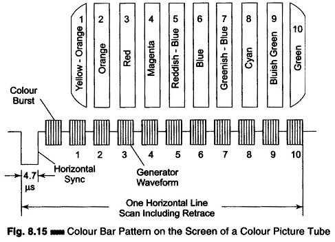
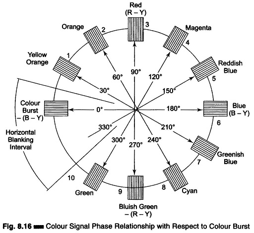
The color bar pattern, the associated video waveform and the corresponding phase relationship of the gated pattern is given in Figs. 8.15 and 8.16 respectively.
Each color in the bar pattern has been identified and lined up with the associated modulated voltage.
The composite video signal for the pattern consists of a horizontal sync pulse and 11 equal amplitude bursts of color sub-carrier frequency. The burst to the right is a color burst; and other bursts from 1 to 10 differ in phase from one another and correspond to different colors in the bar pattern.
The basic principle of a color bar generator is quite simple. Any two signals at different frequencies have a phase difference that changes continuously.
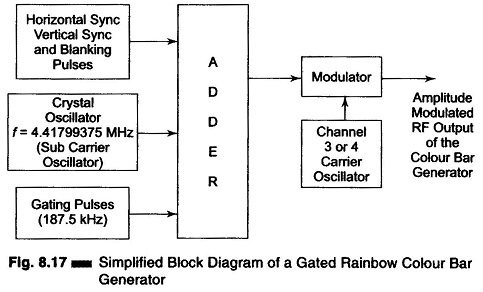
As shown in Fig. 8.17, a crystal oscillator is provided to generate a frequency of 4.41799375 MHz. This is 15625 Hz lower than the color sub-carrier frequency (4.43361875 – 4.41799375 MHz = 15625 Hz). Since the difference in frequency is equal to the horizontal scanning rate, the relative phase between the two carrier frequencies changes by 360° per horizontal line. Thus the effective carrier signal at 4.41799375 MHz will appear as a signal that is continuously changing in phase (360° during each H-line) when compared to the 4.43361875 MHz reference oscillator in the TV receiver. It is the phase of the chrominance signal which determines the color seen, and therefore has a frequency relationship with the subcarrier frequency that provides the color bar signal. Since there is a complete change of phase of 360° for each H-sweep, a complete range of colors is produced during each H-line. Each line displays all the colors simultaneously, since the phase between the frequency of the crystal oscillator and the horizontal scanning rate frequency is zero at the beginning of each such line and advances to become 360° at the end of each horizontal sweep stroke.
The Color Bar Generator is produced by gating On and Off the 4.41799375 MHz oscillator at a rate 12 times higher than the H-sweep frequency (15625 x 12 = 187.5 kHz). The gating at a frequency of 187.5 kHz produces color bars with blanks between them. The color bars have a duration corresponding to 15°, and are 30° apart all around the color spectrum. When viewed on the picture tube screen of a normally operated color receiver, these bars appear as shown in Fig. 8.15.
Only 10 color bars are shown in the screen, because one of the bursts occurs at the same time as the H-sync pulse and is thus eliminated. The adder, while gating the crystal oscillator output, also combines H-sync, V-sync and blanking pulses to the oscillator output. The composite color video signal available at the output of the adder can be fed directly to the chrominance band-pass amplifier in the TV receiver. This signal is usually AM modulated with the carrier of either channel 3 or 4.
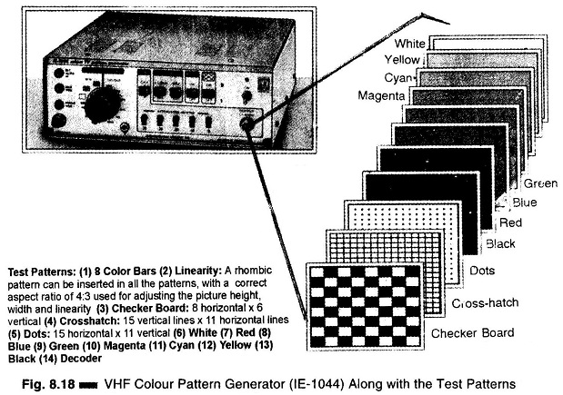
The main technical specifications of a color bar pattern generator are as follows.
Test signals:
- 8 bars, linearized, grey scale
- Cross-hatch pattern
- 100% white pattern (with burst)
- Red pattern (50% saturated)
- Standard color bar with white reference. 75% contrast (internally changeable to full bars).
Video carrier:
- VHF B-III (170 MHz – 230 MHz)
- UHF B-IV (470 MHz – 600 MHz)
RF Output:
≫ 100 mV peak to peak (75 Ω impedance)
Video Modulation:
Amplitude modulation (negative)
Sound carrier:
Frequency – 5.5 MHz (or 6 MHz by internal adjustment)
Modulation – Frequency modulation
Internal signal – 1 kHz sine wave.
FM Sweep 40 kHz on 5.5 MHz
Chroma-PAL-G and I standards
Power:
115 – 230 V; 50 – 60 Hz, 6W
Dimension:
23 x 11 x 21 cm – (w x h x d)
Weight:
1.25 kg
Figure 8.18 illustrates a commercial VHF color pattern generator (IE-1044) along with the various test patterns generated.