Color TV Transmission:
Having discussed the manner of indicating luminance and the two components of chrominance in Color TV Transmission, it is now necessary to investigate how they may be, modulated and sent in the 6-MHz channel, without interference to monochrome TV.
Color Subcarrier and Chroma Modulation:
The actual transmission methods used for the chroma components of the Color TV Transmission system were determined by the following requirements and observations:
-
The sound carrier frequency must remain 4.5 MHz above the picture carrier frequency, because all TV receivers used the intercarrier system of sound detection.
- The energy dispersal of monochrome TV was found to be concentrated, clustered in fact, at harmonics of the line frequency. Significant video energy would be found at frequencies such as 15,750, 31,500, 47,250, 63,000 Hz, .. . 1.575000, 1.590750 MHz, and so on to the 4.2-MHz upper frequency limit for video.
- There was very little video energy at frequencies midway between adjoining line frequency sidebands, such as 39,375 Hz (midway between the second and third sidebands) or at 1.582875 MHz (midway between the 100th and 101st sidebands. Note that these are odd harmonics of one-half the horizontal scanning frequency.
- To arrange for the video voltages due to the chroma signals to fall within these “vacant slots,” it would be necessary to have a color subcarrier frequency which was also an odd multiple of one-half the horizontal scanning frequency.
- To minimise further any possible interference between the chroma and luminance video voltages, it would be a good idea to have the color subcarrier frequency as high as possible.
- The color subcarrier frequency must not be too high, or else:
- It would tend to interfere with the sound subcarrier at 4.5 MHz).
- the video voltages due to chroma would fall outside the 0- to 4.2-MHz video passband of the TV system.
- To reduce further the possibility of interference between the sound subcarrier and video voltages due to color, it would be a good idea to make the sound subcarrier frequency a multiple of the horizontal scanning frequency.
- Since the 4.5-MHz frequency was “untouchable,” it would be necessary to work the other way. The 286th submultiple of 4.5 MHz is 4,500,000/286 = 15,734.26 Hz. This is in fact the horizontal scanning frequency of Color TV Transmission and receivers. It is within 0.1 percent of 15,750 Hz as used in monochrome TV and quite acceptable to that system.
- Since the vertical field frequency is derived from the same oscillator as the horizontal line frequency, this would have to be altered correspondingly. The vertical frequency used in practice by color systems is 59.94 Hz. This is so close to the monochrome frequency as to be perfectly acceptable.
- The eye has much poorer resolution for color than for brightness. It is able to distinguish brightness variation between two adjacent points which are too close for it to be able to note a hue variation between them (as long as their brightness is the same). The chroma video bandwidth need not be as large as the luminance bandwidth.
- The eye’s resolution for colors along the Q axis (reddish-blue-yellowish-green) is only about one-eighth of its luminance resolution, so that a 0.5-MHz bandwidth for the Q signal would suffice. It is able to resolve the colors along the I axis (yellowish-red-greenish-blue) about three times better than that. A 1.5-MHz bandwidth for the I signal would be needed.
- Bandwidth could be saved, and interference minimized, if the I signal were sent by using vestigial-sideband modulation, with the top 1 MHz of its upper sideband suppressed.
- Interference would be further reduced if the color subcarrier frequency were
- The best method of combining the I and Q signals seemed to be the modulation of the same subcarrier by them, with a 90° phase difference between the I and Q
- The (suppressed) color subcarrier should he located so high that the upper sidebands of the signals modulating it (both extending 0.5 MHz from this subcarrier) should come just below the 4.2-MHz upper frequency limit of the video
-
Since the color subcarrier is suppressed, some other form of color synchronization will have to be employed, to ensure correct absolute phases of the / and Q signals in the receiver.
The foregoing considerations have resulted in the use of a color subcarrier frequency that is the 455th harmonic of half the horizontal scanning frequency. Another way of putting it is to say that the color subcarrier frequency is the 277th harmonic of the horizontal frequency plus one-half of the horizontal frequency. Either way, we have
![]()
This is the actual frequency generated. For simplicity, it is normally quoted as 3.58 MHz.
The 3.58-MHz reference signal is sent in the form of a brief pulse, or burst. It is superimposed on top of–the back porch of each horizontal sync pulse. It will be recalled that the duration of this period of horizontal blanking is approximately 6 μs. The burst of 3.58 MHz consists of 8 to 11 complete cycles. These occupy a period not longer than 3.1 μs, so that adequate time is available for its sending. The peak-to-peak amplitude of the burst signal is approximately 15 percent of the percentage modulation ,range of video. Since it is superimposed on the 75 percent modulation blanking level, its peak-to-peak amplitude range stretches from 67.5 percent at the lowest point (top of the black level) to 82.5 percent at the highest point (one-third of the way from blanking to sync tops). It does not interfere with monochrome TV and is usable by a color receiver, as will be seen. Note that the color burst is not sent during the vertical blanking period, during which it is not needed.
Color Transmitters:
The block diagram of a Color TV Transmission is shown in Figure 17-22. This is a simplified block diagram, in which the sections not directly related to Color TV Transmission have been “attenuated.” Note that each block represents a function, not just a single circuit.
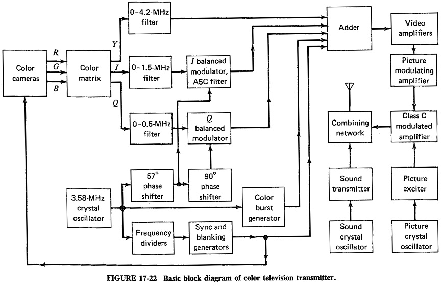
The Y, I and Q outputs from the Color TV Transmission matrix are fed to their respective low-pass filters. These filters attenuate the unwanted frequencies, but they also introduce unwanted phase shifts. Phase-compensating networks (not shown) are inserted after the filters, to produce the correct phase relationships at the balanced modulators.
The output of the Color TV Transmission subcarrier generator is sent in three directions. One of the three outputs is used to synchronize the blanking and sync pulse generators. Their output, in turn, is transmitted as in monochrome TV, and a portion of it is used to synchronize the transmitter cameras, as well as introducing blanking into the transmitted video. The second path for the 3.58-MHz oscillator output is to the color burst generator, which is a fairly complex piece of equipment that ensures the correct transmission (and phase preservation) of the color burst. The last output from this oscillator is fed to a 57° phase shifter, to provide the necessary shift for the I signal. A further 90° phase shift is produced, giving a total of 147° for the Q signal. Note the 90° phase difference between the I and Q signals.
The I balanced modulator produces a double-sideband (suppressed-carrier) signal stretching 1.5 MHz on either side of the 3.58-MHz subcarrier. The vestigial-sideband filter then removes the top 1 MHz from that. The output of the Q balanced modulator is a signal occupying the range of 0.5 MHz below and above the suppressed 3.58-MHz subcarrier. The added 90° phase shift puts this signal in quadrature with the I component; hence the name “Q signal.”
All these signals are fed to the adder, whose output therefore contains:
- The Y luminance signal, occupying the band from 0 to 4.2 MHz, and virtually indistinguishable from the video signal in monochrome TV
- Synchronising and blanking pulses, identical to those in monochrome TV, except that the scanning frequencies have been slightly shifted as discussed, to 15,734.26 Hz for the horizontal frequency and 59.94 Hz for the vertical frequency.
- (Approximately) 8 cycles of the 3.579545-MHz color subcarrier reference burst superimposed on the front porch of each horizontal sync pulse, with an amplitude of ±7.5 percent of peak modulation
- An I chroma signal, occupying the frequency range from 1.5 MHz below to 5 MHz above the color subcarrier frequency, and an energy dispersal occupying the frequency clusters not used by the luminance signal
- A Q chroma signal, occupying the frequency range from 0.5 MHz below to 5 MHz above the color subcarrier frequency, and an energy dispersal occupying the same frequency clusters as the I signal, but with a 90° phase shift with respect to the I signal
The output of the adder then undergoes the same amplifying and modulating processes as did the video signal at this point in a black-and-white transmitter. The signal is finally combined with the output of an FM sound transmitter, whose carrier
frequency is 4.5 MHz above the picture carrier frequency, as in monochrome TV.
It is worth pointing out at this stage that one of the main differences between the PAL system and the NTSC system so far described is that in the PAL system the phase of the I and Q signals is switched after every line. This tends to average out any errors in the phase of hue that may be caused by distortion or noise and tends to make this system somewhat more noise-immune. This phase alternation by line is what gives this system its name.