Travelling Waves on Transmission Lines:
Any disturbance on a Travelling Waves on Transmission Lines or system such as sudden opening or closing of line, a short circuit or a fault results in the development of overvoltages or overcurrents at that point. This disturbance propagates as a travelling wave to the ends of the line or to a termination, such as, a sub-station.
Usually these Travelling Waves on Transmission Lines are high frequency disturbances and travel as waves. They may be reflected, transmitted, attenuated or distorted during propagation until the energy is absorbed. Long transmission lines are to be considered as electrical networks with distributed electrical elements.
In Fig. 8.14, a typical two-wire transmission line is shown along with the distributed electrical elements, R, L, C and G.
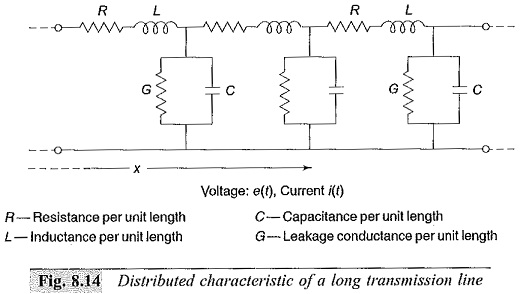
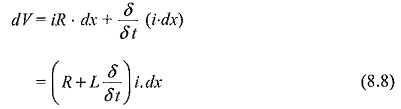
The propagation of any Travelling Waves on Transmission Lines, say a voltage wave can be analysed by considering an elemental length of the line dx. The voltage drop in the positive x-direction in the elemental length dx due to the inductance and resistance is
![]()
Here, δψ is the change of flux linkages and is equal to i.L.dx, where i the current through the line.
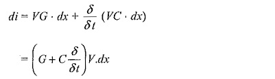
The shunt current through the leakage conductance (G) and capacitance (C) is
![]()
Here, ∇φ is the change in electrostatic field flux and is equal to VC.dx, where V is the potential at the point x.
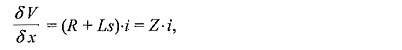
Hence, the above equations can be written as
![]()
Taking Laplace transform with respect to the time variable t, the equations can be put in the operation form as
![]()
Eliminating i and V from above equations and differentiating w.r.t. x, we get
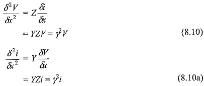
where the product YZ = γ2 = RG + (RC + LG)s + LCs2.
The above two equations are called Wave Equations or Telegraphic Equations. The solutions for the above equations can be written in the form:
![]()
where f1(t) and f2(t) are any arbitrary functions that satisfy the boundary conditions. The operator γ is simplified as
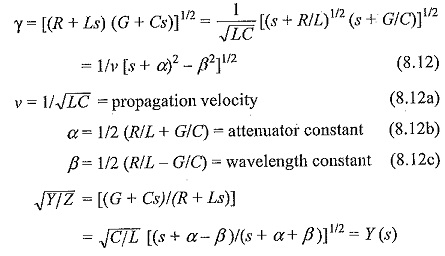
Y(s) is called the surge admittance, the reciprocal of which
![]()
Z (s) is called the surge impedance of the Travelling Waves on Transmission Lines.