Rectangular Travelling Wave:
Reflection and transmission of a Rectangular Travelling Wave at junction points of unequal impedances in a transmission line are of great importance in transmission systems. Depending on the type of impedance at transition points, the Rectangular Travelling Wave is modified, and sometimes a voltage rise or build-up of voltage can occur. The following cases are of practical importance and as such are discussed here. The solution is obtained using the Laplace Transforms rather than using operational calculus, as many of the readers may not be familiar with the Heaviside Operational Calculus.
Cases (i): Open ended transmission line of surge impedance Z:
Let the voltage of Rectangular Travelling Wave incident on the line be
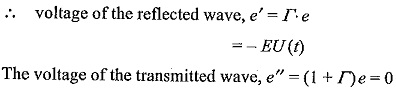
voltage of the reflected wave, e′ = Γe = e = EU(t) and the voltage of the transmitted wave,
![]()
Hence the voltage at the open end rises to double its value.
Case (ii): Short circuited line:
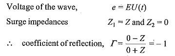
Further i’, the magnitude of the reflected current wave
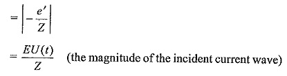
The total current at the junction point![]()
Thus, the current at the junction point rises to double the value of the incident current wave.
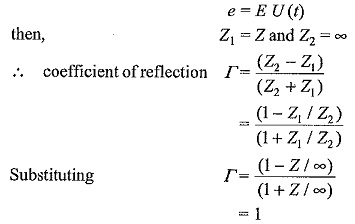
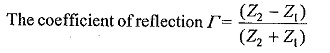
Case (iii): Line terminated with a resistance equal to the surge impedance of the line:
In this case, Z1 = Z and Z2 = R = Z
coefficient of reflection,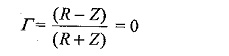
voltage of the reflected wave, e′ is Γ e = 0
The voltage of the transmitted wave is (1 + Γ)e = e
Thus, there is no reflected wave. There is no discontinuity of the line, and the Rectangular Travelling Wave proceeds without reflection and disappears: It is very important to note that there will be no reflections at the junction, if a transmission line or cable is terminated with a resistance equal to the surge impedance of the line or cable.
Case (iv): Line terminated with a capacitor:
In this case, e = EU(t), Z1 = Z, and Z2 = 1/Cs
where s is the Laplace transform operator.
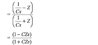
The voltage of the reflected wave, e′ = Γe
Taking the Laplace transform,
Taking the inverse transform
![]()
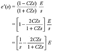
The voltage of the Laplace transformed transmitted wave,
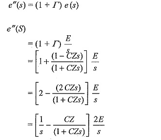
Taking the inverse transforms
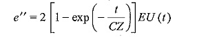
From the expression for e”, it can be inferred that the steepness of the front is reduced and the wave rises slowly in an exponential manner. The capacitor initially acts as a short circuit and is charged through the line impedance Z. The voltage at the junction point finally rises to twice the magnitude of the incident wave.
Case (v): Transmission terminated by an inductance L:
In this case, e = EU(t)
![]()
The coefficient of reflection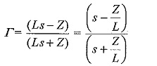
Voltage of the reflected wave, e′ = Γe
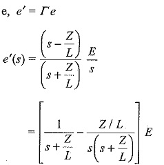
Taking inverse transforms,
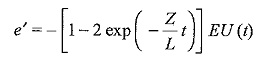
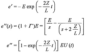
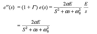
Voltage of the transformed transmitted wave, e″(s) = (1 + Γ) e(s)
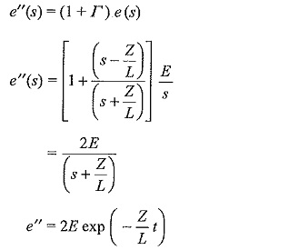
The voltage across the inductor initially rises to double the value of the incident wave and decays exponentially. This is of importance when long lines are terminated with inductors or transformers on open circuit.
Case (vi): Line having a series inductor:
Let the surge impedance of the line be Z before and after the series inductor L. Considering the junction point after the inductor L, e = EU(t), Z1 = (Z + Ls), and Z2 = Z.
The coefficient of reflection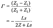
Voltage of the transformed reflected wave, e′(s) = Γ e(s)
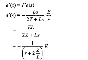
Taking the inverse transform,
As seen from the expression for e”, the steepness of the propagated wave through the inductor, i.e. the transmitted wave into the second portion of the line is reduced. The series inductor produced the same effect as that of a shunt capacitor on a transmission line.
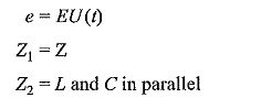
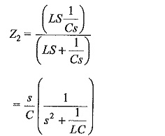
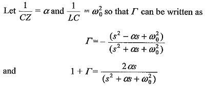
Case (vii): Line terminated with a transformer (taken as an L-C parallel combination):
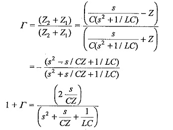
coefficient of reflection,
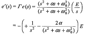
The reflected wave,
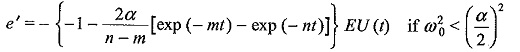
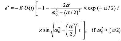
Taking the inverse transform,
The transmitted wave,
Taking the inverse transform,
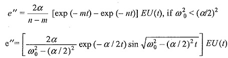
The transmitted wave reaching the transformer will be either a double exponential (standard impulse type) or a damped sinusoidal wave and the steepness of the wave front gets reduced.
The above analysis shows that Rectangular Travelling Wave is modified at the transition points, and the steepness of the wave front is reduced in certain cases. There can be doubling effect at the junction points such as an open ended line or an inductance termination. These also contribute for further overvoltages at the transition points in a transmission system.