Rectangular Waveguides:
Rectangular Waveguides – As we know already that the term skin effect indicated that the majority of the current flow (at very high frequencies) will occur mostly along the surface of the conductor and very little at the center. This phenomenon has led to the development of hollow, conductors known as waveguides.
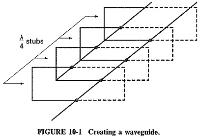
To simplify the understanding of the waveguide action, which explained how the quarter-wave shorted stub appeared as a parallel resonant circuit (Hi Z) to the source. This fact can be used in the analysis of a wave guide; i.e., a transmission line can be transformed into a waveguide by connecting multiple quarter-wave shorted stubs (see Figure 10-1). These multiple connections represent a Hi Z to the source and offer minimum attenuation of a signal.
In a similar way, a pipe with any sort of cross section could be used as a waveguide, but the simplest cross sections are preferred. Waveguides with constant rectangular or circular cross sections are normally employed, although other shapes may be used from time to time for special purposes. With regular transmission lines and waveguides, the simplest shapes are the ones easiest to manufacture, and the ones whose properties are simplest to evaluate.
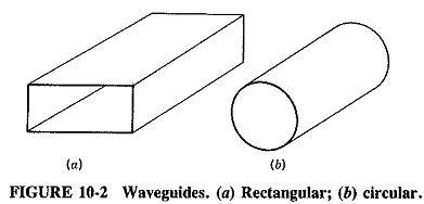
A rectangular waveguides is shown in Figure 10-2, as is a circular waveguide for comparison. In a typical system, there may be an antenna at one end of a waveguide and a receiver or transmitter at the other end. The antenna generates electromagnetic waves, which travel down the waveguide to be eventually received by the load.
The walls of the guide are conductors, and therefore reflections from them take place. It is of the utmost importance to realize that conduction of energy lakes place not through the walls, whose function is only to confine this energy, but through the dielectric filling the waveguide, which is usually air. In discussing the behavior and properties of waveguides, it is necessary to speak of electric and magnetic fields, as in wave propagation, instead of voltages and currents, as in transmission lines. This is the only possible approach, but it does make the behavior of waveguides more complex to grasp.
Applications of Rectangular Waveguides:
Because the cross-sectional dimensions of a waveguide must be of the same order as those of a wavelength, use at frequencies below about 1 GHz is not normally practical, unless special circumstances warrant it. Some selected waveguide sizes, together with their frequencies of operation, are presented in Table 10-1.
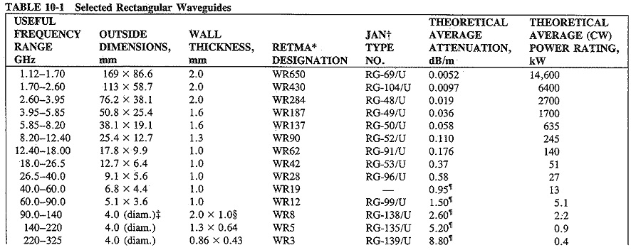
The table shows how waveguide dimensions decrease as the frequency is increased (and therefore wavelength is shortened). It does not show the several waveguides larger than the WR650, nor does it show many of the overlapping sizes that are also made. Note that the reason for the rather odd dimensions is that waveguides originally were made to imperial measurements (e.g. , 3.00 x 1.50 in) and have subsequently been relabeled in millimeters, not remade in round millimeter sizes. It is seen that waveguides have dimensions that are convenient in the 3- to 100-GHz range, and somewhat inconvenient much outside this range. Within the range, waveguides are generally superior to coaxial transmission lines for a whole spectrum of microwave applications, for either power or low-level signals.
Both waveguides and transmission lines can pass several signals simultaneously, but in waveguides it is sufficient for them to be propagated in different modes to be separated. They do not have to be of different frequencies. A number of waveguide components are similar if not identical to their coaxial counterparts. These components include stubs, quarter-wave transformers, directional couplers, and taper sections. Finally, the Smith chart may be used for waveguide calculations also. The operation of a very large number of waveguide components may best be understood by first looking at their transmission-line equivalents.
Advantages of Rectangular Waveguides:
The first thing that strikes us about the appearance of a (circular) waveguide is that it looks like a coaxial line with the insides removed. This illustrates the advantages that waveguides possess. Since it is easier to leave out the inner conductor than to put it in, waveguides are simpler to manufacture than coaxial lines. Similarly, because there is neither an inner conductor nor the supporting dielectric in a waveguide, flashover is less .likely. Therefore the power-handling ability of waveguides is improved, and is about 10 times as high as for coaxial air-dielectric rigid cables of similar dimension (and much more when compared with flexible solid-dielectric cable).
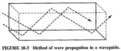
There is nothing but air in a waveguide, and since propagation is by reflection from the walls instead of conduction along them, power losses in waveguides are lower than in comparable transmission lines (see Figure 10-3). A 41-min air-dielectric cable has an attenuation of 4.0 dB/100 m at 3 GHz (which is very good for a coaxial line). This rises to 10.8 dB/100 m for a similar foam-dielectric flexible cable, whereas the figure for the copper WR284 waveguide is only 1.9 dB/ 100 m.
Everything else being equal, waveguides have advantages over coaxial lines in mechanical simplicity and a much higher maximum operating frequency (325 GHz as compared with 18 GHz) because of the different method of propagation.